
Automobile sensor production device

A production equipment and sensor technology, applied in the field of automotive sensor production equipment, can solve the problems of reduced production efficiency, long drying time, lack of shock absorption function, etc., and achieve the effect of improving practicability and stability

Inactive Publication Date: 2021-01-05
克莱门斯工业传感器南京有限公司
View PDF9 Cites 0 Cited by
  • Summary
  • Abstract
  • Description
  • Claims
  • Application Information

AI Technical Summary

Problems solved by technology

[0004] The purpose of the present invention is to solve the problem that the existing drying equipment does not have the shock-absorbing function, the equipment is prone to shake during the working process, and the stability is not high. At the same time, the existing drying equipment, when drying the sensor , it cannot be dried evenly, resulting in too long drying time, which reduces the production efficiency, and the proposed automotive sensor production equipment

Method used


Image

  • Automobile sensor production device
  • Automobile sensor production device
  • Automobile sensor production device

Examples


Embodiment 1

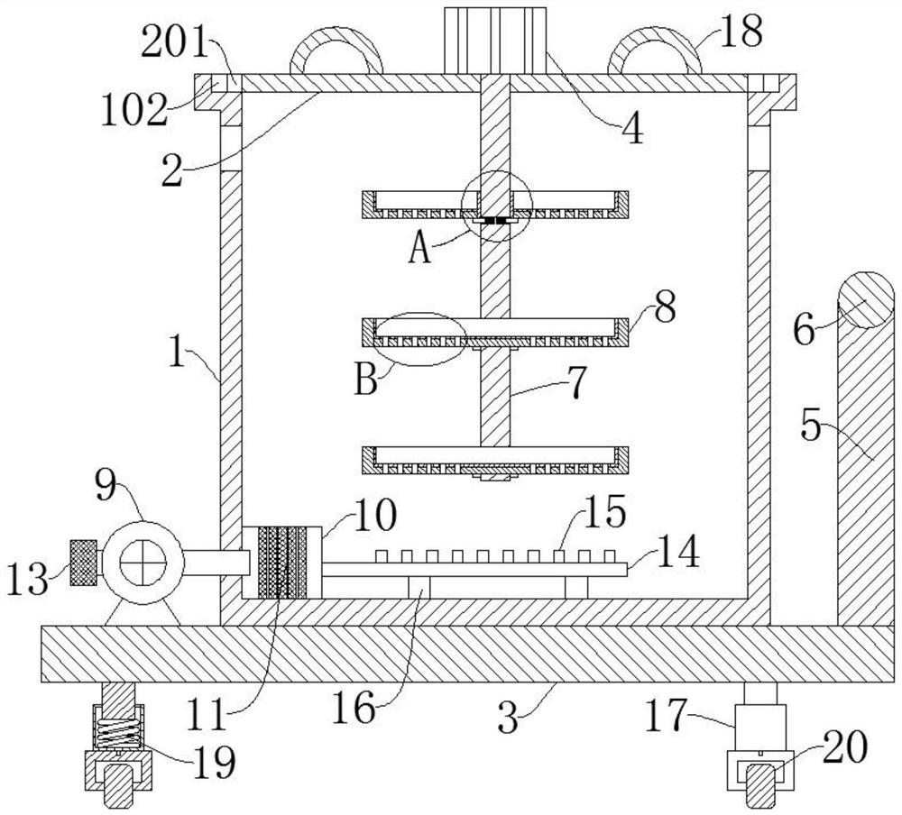
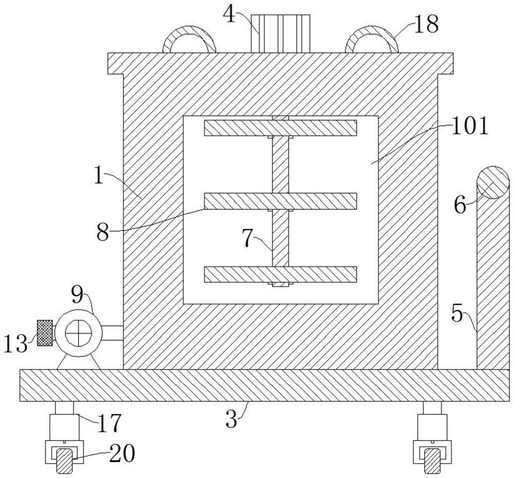
[0028]ReferenceFigure 1-5, Automotive sensor production equipment, including a box body 1, the upper end of the box body 1 is connected with a box cover 2, the box cover 2 is fixedly connected with a first motor 4, the output end of the first motor 4 is fixedly connected with a rotating rod 7, the rotating rod 7 penetrates through the box cover 2, a plurality of placing plates 8 are connected to the rotating rod 7 by screwing, and the placing plate 8 is provided with a placing groove, the bottom of the placing groove is provided with a ventilation hole 801, and the inner bottom side of the box body 1 is fixedly connected with A drying box 10, a heating plate 11 is fixedly connected to the drying box 10, a ventilation pipe 14 is fixedly connected to one side of the drying box 10, and a plurality of nozzles 15 are arranged on the ventilation pipe 14 and matched with the position of the placing plate 8. The lower end of the box body 1 is fixedly connected with a base 3, and the upper e...

Embodiment 2

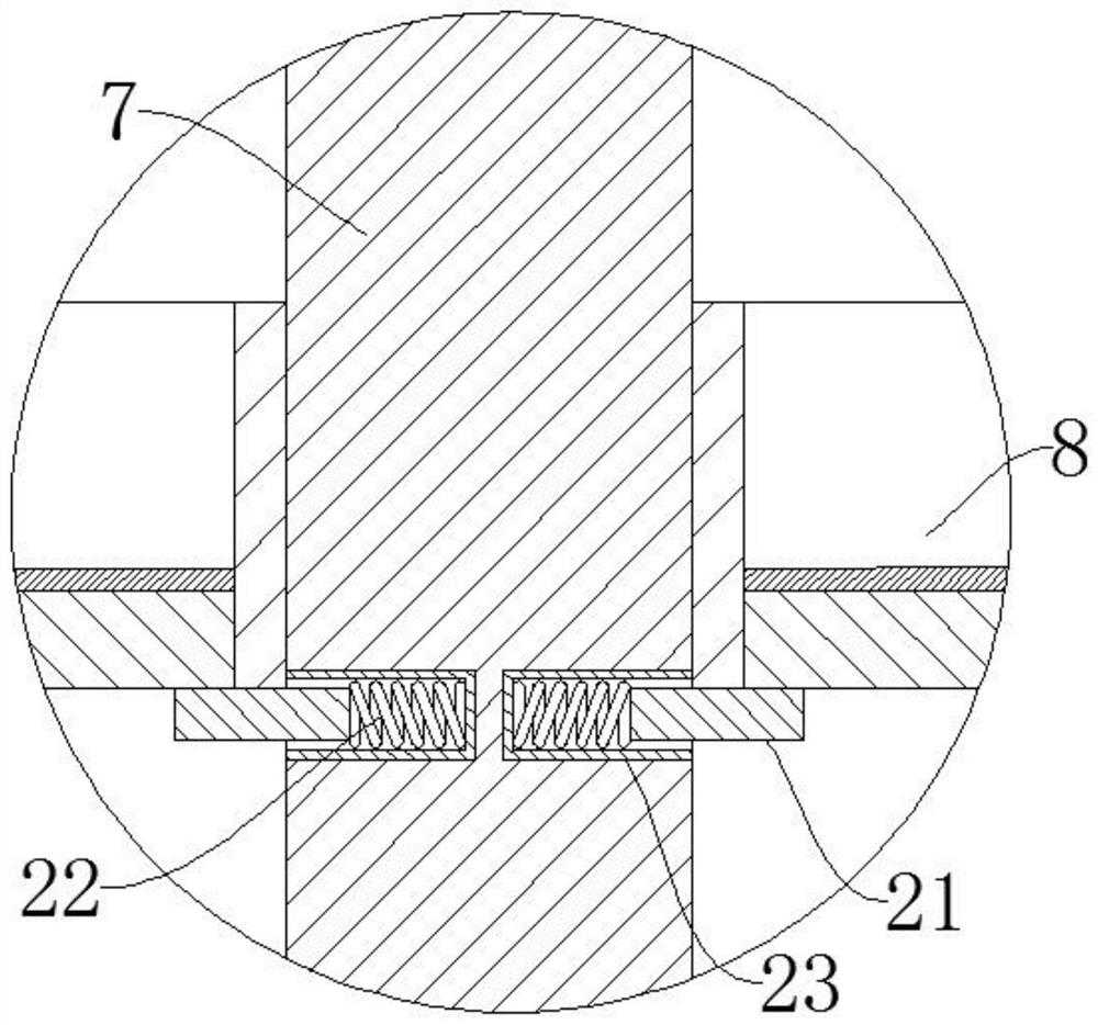
[0031]ReferenceFigure 1-5The automobile sensor production equipment is basically the same as that of the first embodiment. Furthermore, the rotating rod 7 is provided with two symmetrical grooves 23. The grooves 23 are fixedly connected with a return spring 22, and the return spring 22 is far away One end of the bottom of the groove 23 is fixedly connected to the limit rod 21, which effectively prevents the placement plate 8 from moving downwards when rotating, and then falls off the rotating rod 7, which acts as a limiter and improves the stability of the device .

Embodiment 3

[0033]ReferenceFigure 1-5, The production equipment for automotive sensors is basically the same as that of the first embodiment. Furthermore, the two ends of the box cover 2 are fixedly connected with first magnetic blocks 201, and both sides of the upper end of the box body 1 are provided with matching first magnetic blocks 201. The second magnetic block 102 can prevent the cover 2 from shaking during operation, which further improves the stability of the device.


PUM


Abstract

The invention discloses an automobile sensor production device, and belongs to the technical field of sensor production equipment. The automobile sensor production device comprises a box body, whereinthe upper end of the box body is connected with a box cover; the box cover is fixedly connected with a first motor; the output end of the first motor is fixedly connected with a rotating rod; the rotating rod is rotatably connected with a plurality of placing plates through threads; placing grooves are formed in the placing plates; ventilation holes are formed in the bottoms of the placing grooves; the lower end of the box body is fixedly connected with a base; the two sides of the lower end of the base are fixedly connected with telescopic rods; and damping springs are fixedly connected in the telescopic rods. According to the automobile sensor production device, the damping springs are arranged, so that the damping effect on the device is achieved, the device is prevented from shaking in the working process, the drying efficiency is prevented from being influenced, and the stability of the device is improved; and the first motor and the ventilation holes are arranged, so that the device can be used for drying a sensor more uniformly, and the drying efficiency of the device is improved.

Description

Technical field[0001]The invention relates to the technical field of sensor production equipment, in particular to sensor production equipment for automobiles.Background technique[0002]Automobile sensor is a detection device that can feel the information being measured, and can transform the sensed information into electrical signals or other required forms of information output according to certain rules, so as to meet the needs of information transmission, processing, storage, and Display, record and control requirements.[0003]Automotive sensors need to be dried during the manufacturing process. However, the existing drying equipment does not have the function of damping. The equipment is prone to shaking during the working process, and the stability is not high. At the same time, the existing drying equipment The drying equipment, when drying the sensor, cannot evenly dry it, resulting in too long drying time, thereby reducing production efficiency.Summary of the invention[0004]T...

Claims


Application Information

Patent Timeline
Patent Type & Authority Applications(China)
IPC IPC(8): F26B11/18F26B21/00F26B25/08F26B25/12F26B25/18
CPCF26B11/182F26B21/001F26B21/003F26B21/004F26B25/08F26B25/12F26B25/18
Inventor 吴玉荣
Owner 克莱门斯工业传感器南京有限公司
Learn More