
Safety monitoring device for Internet of Things access of street lamp pole

A technology for safety monitoring and street light poles, applied in measuring devices, lighting devices, circuit layout, etc., can solve the problems of increasing maintenance costs, hurting pedestrians, and the difficulty of component contact and coordination to achieve a reasonable structure, etc.

Pending Publication Date: 2021-01-05
常州市城市照明工程有限公司
View PDF0 Cites 0 Cited by
  • Summary
  • Abstract
  • Description
  • Claims
  • Application Information

AI Technical Summary

Problems solved by technology

Street lamp poles and lamp holders are separate components. Generally, street lamp lamp holders are connected and fixed by plugging, threaded jacking screws or fastening cards and bolts. However, since street lamp lamp poles and lamp holders are usually produced by different manufacturers, in Difficult to achieve structural rationality in terms of component contact and fit
At the same time, because the installation of the lamp holder is a manual operation, there are still inconsistencies in the installation and fastening fastness, and the differences in design, material and processing technology of fasteners from different manufacturers used in the installation process will also cause certain problems. Security risks
[0003] For the new-type LED street lamp caps that are being gradually popularized and used at present, due to the large heat generated by the light source, a larger and heavier metal heat sink must be installed on the lamp cap to dissipate heat for it to work reliably for a long time, so the weight of the lamp cap is often It is several times more than traditional street lamps, which increases the risk of lamp head falling
When the lamp head is without warning, a sudden fall will not only injure passers-by, damage the ground environment, but also easily cause damage to the internal structure of the lamp head, thereby increasing maintenance costs

Method used


Image

  • Safety monitoring device for Internet of Things access of street lamp pole
  • Safety monitoring device for Internet of Things access of street lamp pole

Examples


Embodiment Construction

[0020] The present invention will be further described below in conjunction with accompanying drawing:

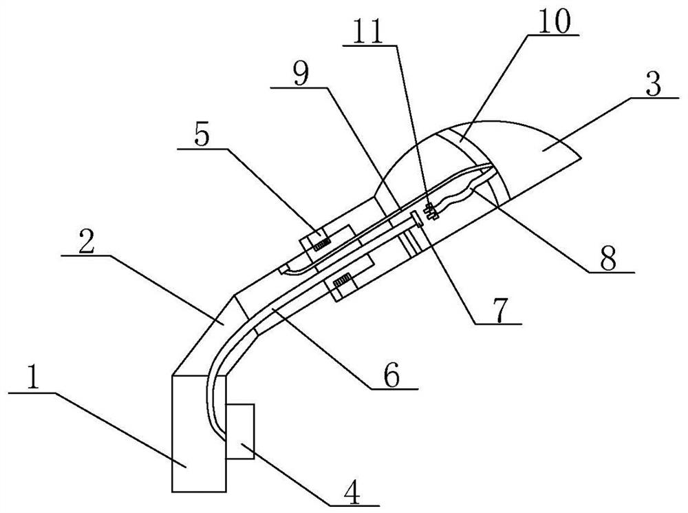
[0021] Such as Figure 1-2 As shown, the present invention includes a light pole 1, a light arm 2 fixedly installed on the top of the light pole 1, and a lamp 3 arranged at the front end of the light arm 2. The light pole 1 is provided with an IoT security monitoring terminal 4 for Intelligently monitor the connection stability of the main components in the street light pole and provide early warning functions for various emergencies.

[0022] A sensing device 5 is provided on the lamp arm 2 and at the front end of the lamp 3, and the sensing device 5 is one or more of a displacement sensor, a pressure sensor or a strain sensor; the sensing device 5 is connected to the IoT Security Monitoring terminal 4, so that once it is found that the fixed end of the lamp 3 on the lamp arm 2 cracks or slides, the sensing device immediately transmits the sensed fault signal to the secur...


PUM


Abstract

The invention discloses a safety monitoring device for Internet of Things access of street lamp pole, which comprises a lamp pole, a lamp arm fixedly installed at the top of the lamp pole and a lamp arranged at the front end of the lamp arm, an Internet of Things safety monitoring terminal is arranged on the lamp pole, and a sensing device is arranged on the lamp arm and located at the front end of the lamp. The sensing device is connected into the Internet of Things safety monitoring terminal through a circuit, an anti-falling lead is arranged in the lamp arm, one end of the anti-falling leadis connected into the Internet of Things safety monitoring terminal, a socket is installed at the other end of the anti-falling lead, a cable and a steel rope are arranged in the lamp, and one end ofthe cable is fixed to a main body frame in the lamp. One end of the steel rope is fixed to the main body frame, and the other end of the steel rope is fixed to the inner wall of the lamp arm, whereinthe length of the steel rope is larger than that of the cable. All-weather monitoring and protection can be carried out on the lamp, and the lamp is prevented from suddenly falling to smash any object or life body under the lamp under the condition that no early warning exists.

Description

technical field [0001] The invention relates to the technical field of street light poles, in particular to a safety monitoring device connected to street light poles. Background technique [0002] At present, street lamps generally adopt the structural form of installing lamp caps on light poles of different shapes and heights. Street lamp poles and lamp holders are separate components. Generally, street lamp lamp holders are connected and fixed by plugging, threaded jacking screws or fastening cards and bolts. However, since street lamp lamp poles and lamp holders are usually produced by different manufacturers, in It is difficult to achieve structural rationality in terms of component contact and fit. At the same time, because the installation of the lamp holder is a manual operation, there are still inconsistencies in the installation and fastening fastness, and the differences in design, material and processing technology of fasteners from different manufacturers used ...

Claims


Application Information

Patent Timeline
IPC IPC(8): F21S8/08F21V15/00F21V23/00F21V23/04F21V33/00G01D21/02F21W131/103F21Y115/10
CPCF21S8/086F21V15/00F21V23/003F21V23/0435F21V23/0442F21V33/00F21V33/0076F21W2131/103F21Y2115/10G01D21/02
Inventor 刘锁龙
Owner 常州市城市照明工程有限公司
Learn More