Tunneling hydraulic cylinder

A hydraulic cylinder and main body technology, applied in the field of hydraulic cylinders, can solve the problems of increasing the load of the excavation hydraulic cylinder, wear of the piston rod, affecting the sealing of the excavation hydraulic cylinder, etc., and achieve the effect of reducing friction

Pending Publication Date: 2021-01-05
韩振华
View PDF0 Cites 2 Cited by
  • Summary
  • Abstract
  • Description
  • Claims
  • Application Information

AI Technical Summary

Problems solved by technology

[0004] Aiming at the problems in the prior art, the present invention provides a hydraulic cylinder for excavation, which solves the problem that no protective structure is installed on the outside of the hydraulic cylinder for excavation currently used, and the piston rod of the hydraulic cylinder for excavation is easily deformed due to the impact of external force. As a result, the piston rod of the excavation hydraulic cylinder cannot be stretched normally. If the surrounding air of the excavation hydraulic cylinder contains a lot of foreign matter such as dust, when the piston rod of the excavation hydraulic cylinder is moving, foreign matter such as dust in the air is likely to stick to the On the piston rod of the excavation hydraulic cylinder, when the piston rod of the excavation hydraulic cylinder is recovered, foreign matter such as dust will be brought into the interior of the excavation hydraulic cylinder, which is easy to damage the piston of the excavation hydraulic cylinder, thereby affecting the sealing of the excavation hydraulic cylinder. If the surrounding air of the excavation hydraulic cylinder is relatively dry, the surface of the piston rod of the excavation hydraulic cylinder is relatively dry, and the friction force generated during the movement is relatively large, which increases the load of the excavation hydraulic cylinder and easily causes the wear of the piston rod on the outer wall of the excavation hydraulic cylinder. question

Method used


Image

  • Tunneling hydraulic cylinder
  • Tunneling hydraulic cylinder
  • Tunneling hydraulic cylinder

Examples


Embodiment Construction

[0026] In order to make the technical means, creative features, goals and effects achieved by the present invention easy to understand, the present invention will be further described below in conjunction with specific embodiments.

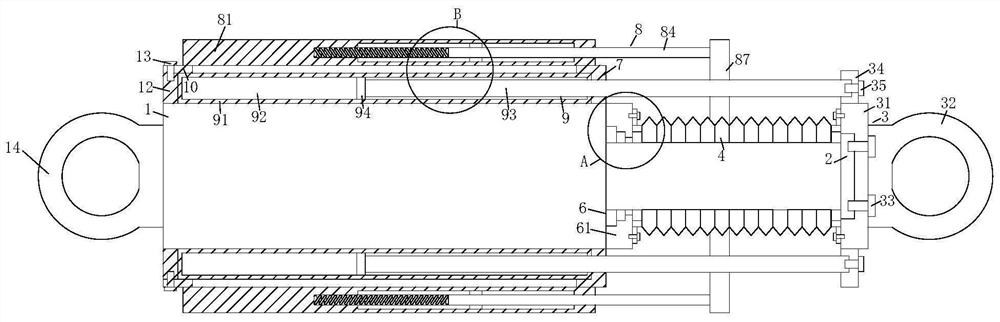
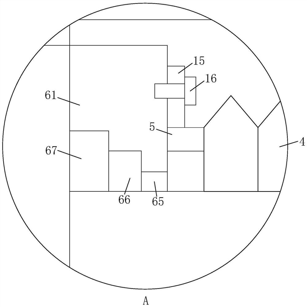
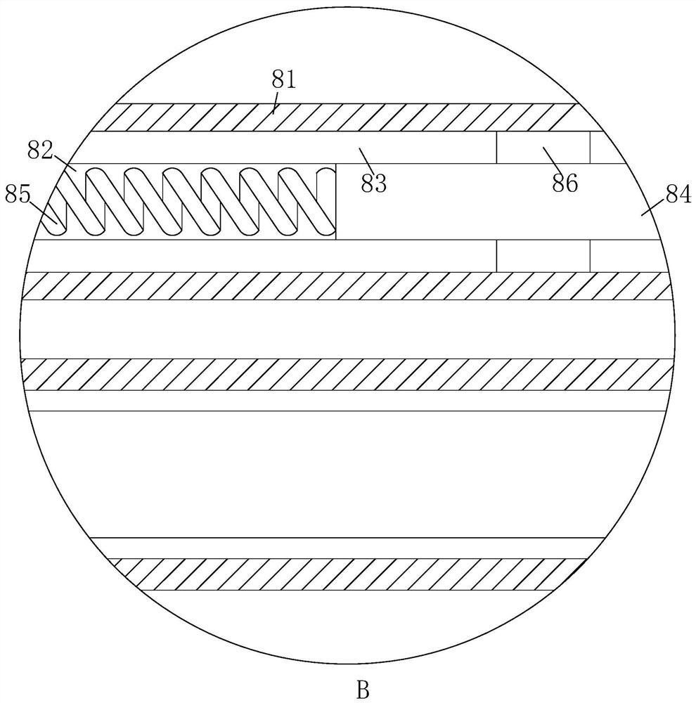
[0027] like Figure 1-Figure 7As shown, an excavation hydraulic cylinder according to the present invention includes a hydraulic cylinder main body 1, the piston rod of the hydraulic cylinder main body 1 is located on one side of the hydraulic cylinder main body 1 and the moving end of the piston rod is fixedly connected with a mounting plate 2, A connecting head 3 is installed on the mounting plate 2, and a dust-proof pipe 4 is set on the outside of the piston rod of the hydraulic cylinder main body 1. Both ends of the dust-proof pipe 4 are fixedly connected with a connecting ring 5, and the connecting ring 5 is sleeved and fixedly connected with a second fixed ring 15 on the outer wall of the circumference of 5, and the fourth bolt 16 is threade...


PUM


Abstract

The invention relates to the field of hydraulic cylinders, in particular to a tunneling hydraulic cylinder which comprises a hydraulic cylinder body. A piston rod of the hydraulic cylinder body is located on one side of the hydraulic cylinder body, a mounting plate is fixedly connected to the moving end of the piston rod, a connector is mounted on the mounting plate, and the piston rod of the hydraulic cylinder body is sleeved with a dustproof pipe. Connecting rings are fixedly connected to the two ends of the dustproof pipe, the circumferential outer walls of the connecting rings are both fixedly connected with second fixing rings in a sleeved mode, and the second fixing rings are both in threaded connection with fourth bolts. Auxiliary mechanisms and protection mechanisms are arranged outside the hydraulic cylinder body; when the hydraulic cylinder is in use, sliding rods of the auxiliary mechanisms and protection rods of the protection mechanisms surround the outer portion of the piston rod of the hydraulic cylinder body; and when the hydraulic cylinder is subjected to external impact, acting force generated during impact can act on the sliding rods and the protection rods firstly, the sliding rods and the protection rods can buffer the acting force, and the situation that since external impact force directly acts on the piston rod of the hydraulic cylinder body, the pistonrod of the hydraulic cylinder body deforms is prevented.

Description

technical field [0001] The invention relates to the field of hydraulic cylinders, in particular to a driving hydraulic cylinder. Background technique [0002] A hydraulic cylinder is a hydraulic actuator that converts hydraulic energy into mechanical energy and performs linear reciprocating motion (or swing motion). Many mechanical equipment are equipped with hydraulic cylinders. [0003] At present, there is no protective structure installed on the outside of the excavation hydraulic cylinder. The piston rod of the excavation hydraulic cylinder is easily deformed due to the impact of external force, so that the piston rod of the excavation hydraulic cylinder cannot be stretched normally. If the surrounding air of the excavation hydraulic cylinder When the piston rod of the excavation hydraulic cylinder is in motion, the foreign matter such as dust in the air is easy to stick to the piston rod of the excavation hydraulic cylinder. When the piston rod of the excavation hydrau...

Claims


Application Information

Patent Timeline
Patent Type & Authority Applications(China)
IPC IPC(8): F15B15/14F15B15/20F16J15/52F16N7/12
CPCF15B15/1423F15B15/1461F16J15/52F16N7/12
Inventor 韩振华张波
Owner 韩振华
Why Eureka
Try Eureka