Tube bundle device and use thereof

A device and pipeline technology, applied in the field of tube bundle equipment, can solve the problems of pipeline deformation, medium overflowing into the environment, and different longitudinal expansion.

Active Publication Date: 2015-12-02
BASF SE
View PDF5 Cites 0 Cited by
  • Summary
  • Abstract
  • Description
  • Claims
  • Application Information

AI Technical Summary

Problems solved by technology

[0006] A disadvantage of the known tube bundle arrangement is that, in particular when there is a large temperature difference between the medium in the throughflow line and the medium in the circulation line, the longitudinal expansion of the tubes and the housing differs, so that the tubes can be deformed in the tube bundle arrangement
Also, it is often not easy to replace the tubing from the bundle when needed or when cleaning the bundle or casing
[0007] To avoid this deformation, compensators are usually used on the housing side of the device, but compensators can only be used in devices with limited wall thickness in the low pressure range
The compensator is a known weak point of this construction, failure of which can result in spillage of the medium in the enclosure space into the environment

Method used


Image

  • Tube bundle device and use thereof
  • Tube bundle device and use thereof
  • Tube bundle device and use thereof

Examples


Embodiment Construction

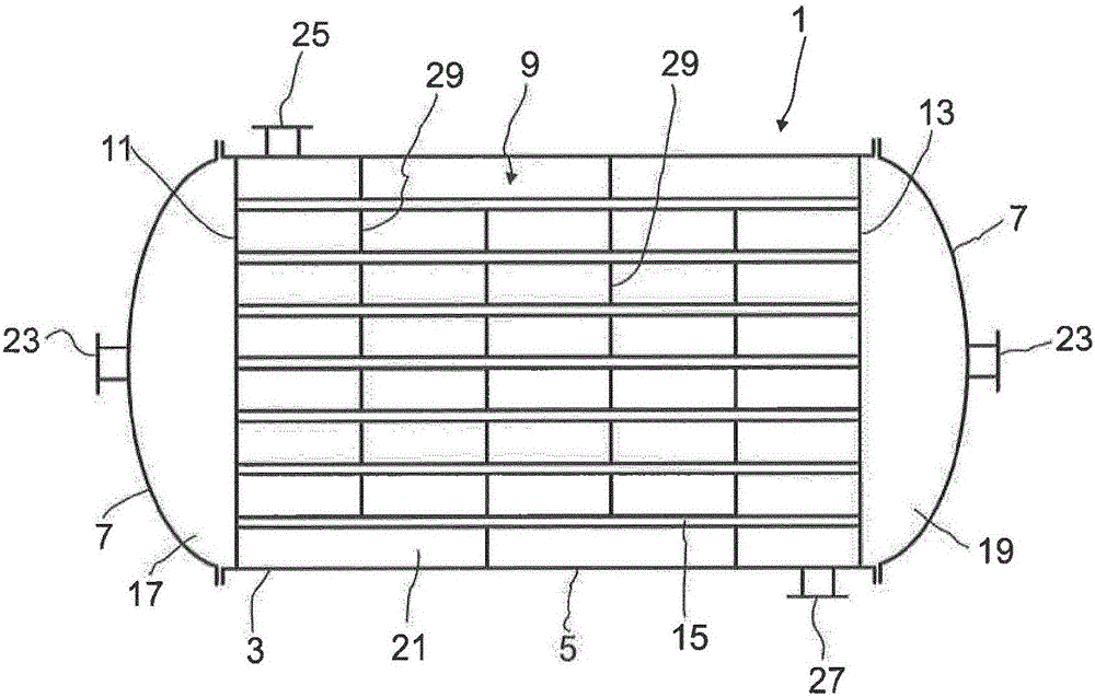
[0032] figure 1 The tube bundle equipment is shown in section.

[0033] The tube bundle arrangement 1 comprises a housing 3 which has a housing 5 which is closed at both ends by a cover 7 . The housing 5 is generally cylindrical here, but it can also have any other cross-section besides a circular cross-section.

[0034] The top cover 7 is usually fastened to the housing 5 respectively by means of a flange connection.

[0035] A tube bundle 9 is accommodated in the housing 3 . The tube bundle 9 comprises a first tube base 11 , a second tube base 13 and pipes 15 . The pipes 15 are here fastened with their ends in one of the two pipe bases 11 , 13 . In this case, the pipes 15 are preferably fixed in the tube bases 11 , 13 in such a way that they each end flush with the tube bases 11 , 13 . This prevents liquid from standing on the tube floor and not being able to flow into the pipe 15 during the vertical operation of the tube bundle arrangement 1 .

[0036] The tube bases ...


PUM


Abstract

The invention relates to a tube bundle device, comprising a housing (3) having a tube bundle (9) accommodated therein, which tube bundle comprises tubes (15), which are connected to a first tube sheet (11) at one end and to a second tube sheet (13) at the end opposite the first tube sheet (11), wherein the first and second tube sheets (11, 13) are detachably fastened in the housing (3). The first tube sheet (11) is supported on a stop (31) on the housing (3) by means of the side of the first tube sheet opposite the tubes (15) and is fastened to the stop (31), and the second tube sheet (13) is guided in the housing (3) by means of a sealing element (41). The invention further relates to a use of the tube bundle device.

Description

technical field [0001] The invention relates to a tube bundle apparatus comprising a housing having a tube bundle accommodated therein with pipes connected at one end to a first tube base and at the other end opposite to the first tube base Connected to the second tube base, wherein the first and second tube bases are detachably fixed in the housing. [0002] The invention also relates to the use of tube bundle devices. Background technique [0003] Tube-bundle devices are often used where heat transfer from a first medium to a second medium is necessary. Such devices are, for example, heat exchangers or reactors. In the tube bundle equipment, the first medium flows through the pipe, and the space around the second medium flows through the pipe. Fluid transfer can be in direct current, convective, cross direct current or cross convection. For the flow guidance of the cross direct current or cross convection mode, each pipe of the tube bundle equipment is guided by a defl...

Claims


Application Information

Patent Timeline
IPC IPC(8): F28F9/02F28D7/16
CPCF28D7/16F28F9/0226F28F9/026
Inventor W·贡克尔F-F·帕佩K·富盖
Owner BASF SE
Why Eureka
Try Eureka