
Welding clamp device for hoisting section of steel plate composite beam bridge and clamping method of welding clamp device

A welding jig and jig device technology, applied in the field of steel plate girder bridge manufacturing, can solve the problems of non-destructive testing and construction quality affecting the welding quality of the ring seam of the bridge position of the hoisting segment, the difficulty of on-site welding operations, and the large number of parts, etc. Improve on-site welding quality, safe and reliable use, and strong practicability

Pending Publication Date: 2021-01-05
CHINA RAILWAY BAOJI BRIDGE GRP
View PDF0 Cites 0 Cited by
  • Summary
  • Abstract
  • Description
  • Claims
  • Application Information

AI Technical Summary

Problems solved by technology

[0002] In the manufacture of curved steel plate girder bridges, most of the manufacturing lines are located on circular curves, transitional curves, and vertical curves, and the number of parts is large, and the overall line shape is relatively complicated
For steel members with a beam height greater than 2 meters, due to the limited working space of the bridge position and the constraints of the erection conditions, the on-site welding operation becomes more difficult, which affects the welding quality of the bridge position ring seam of the hoisting segment and the non-destructive Check construction quality

Method used


Image

  • Welding clamp device for hoisting section of steel plate composite beam bridge and clamping method of welding clamp device
  • Welding clamp device for hoisting section of steel plate composite beam bridge and clamping method of welding clamp device
  • Welding clamp device for hoisting section of steel plate composite beam bridge and clamping method of welding clamp device

Examples


Embodiment Construction

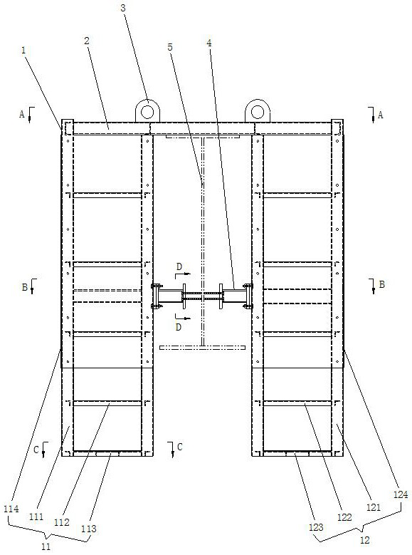
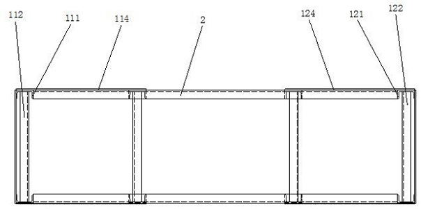
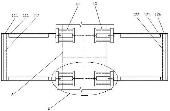
[0032] Such as Figures 1 to 7 As shown, the steel plate composite girder bridge hoisting section welding fixture device of the present invention includes a stand 1 , a beam 2 , a lug plate 3 and a clamping mechanism 4 .

[0033] The stand 1 is vertically placed and includes a first stand 11 and a second stand 12 , the first stand 11 and the second stand 12 have identical structures and are arranged symmetrically to each other.

[0034]The first stand 11 is a cuboid frame structure and is composed of four first columns 111, a first ladder 112, a first back cover 113 and a first baffle 114; The upper ends of the two first columns 111 on the left side of a stand 11 are higher than the upper ends of the two first columns 111 on the right side of the first stand 11; A plurality of first ladders 112 are horizontally connected between two adjacent first columns 111, and the plurality of first ladders 112 are evenly distributed from top to bottom; end; the first baffle 114 is match...


PUM


Abstract

The invention relates to a welding clamp device for a hoisting section of a steel plate composite beam bridge and a clamping method of the welding clamp device. The clamp device comprises a vertical frame, a cross beam, a lifting lug plate and a clamping mechanism. The welding clamp device can be recycled, is convenient to disassemble and assemble on site, is beneficial to saving the production and manufacturing cost and improving the on-site production efficiency, provides safety guarantee for bridge site high-altitude operation, is safe, reliable, convenient, easy to implement and high in practicability, and can ensure that the manufacturing quality and the erecting precision of the hoisting section of the steel plate beam bridge meet the standard requirements. The clamping method of thewelding clamp device for the hoisting section of the steel plate composite beam bridge is simple in operation process, the hoisting section can be conveniently implemented on a bridge site girth welding and nondestructive testing operation site, various technological parameters can meet the standard requirements, the bridge site erecting precision of the hoisting section of the large steel platecomposite beam bridge is ensured to meet the standard requirements, and the on-site welding quality of steel bridge beam manufacturing is improved.

Description

technical field [0001] The invention relates to the technical field of steel plate girder bridge manufacturing, in particular to a steel plate composite girder bridge hoisting section welding fixture device and a clamping method thereof. Background technique [0002] In the manufacture of curved steel plate girder bridges, most of the manufacturing lines are located on circular curves, transitional curves, and vertical curves, and the number of parts is large, and the overall line shape is relatively complicated. For steel members with a beam height greater than 2 meters, due to the limited working space of the bridge position and the constraints of the erection conditions, the on-site welding operation becomes more difficult, which affects the welding quality of the bridge position ring seam of the hoisting segment and the non-destructive Check construction quality. Therefore, how to take reasonable and feasible technological measures to ensure that the manufacturing quali...

Claims


Application Information

Patent Timeline
IPC IPC(8): B23K37/04
CPCB23K37/0435
Inventor 梁晶朱新华田刚毅车平张鹏
Owner CHINA RAILWAY BAOJI BRIDGE GRP
Learn More