Multi-tube cyclone dust removal device

A technology of cyclone dust removal and cyclone dust collector, which is applied in the separation of dispersed particles, chemical instruments and methods, separation methods, etc., can solve the problems of reducing equipment life, accidents, damage, etc., to avoid poor processing accuracy, improve processing capacity, Guarantee the effect of dust removal efficiency

Pending Publication Date: 2021-01-05
WUHAN INSTITUTE OF TECHNOLOGY +1
View PDF0 Cites 0 Cited by
  • Summary
  • Abstract
  • Description
  • Claims
  • Application Information

AI Technical Summary

Problems solved by technology

Workers technically wear dust masks that have the ability to absorb dust, but dust less than 10 μm is still in contact with the human body, and the dust further enters the respiratory system and digestive system through the nasal cavity or mouth, which will cause different degrees of harm to the human body. Direct contact with the skin will also cause certain damage, and the dust in the air will also cause harm to machinery and electronic equipment. The accumulation of dust inside the equipment will greatly reduce the life of the equipment, and accidents will occur in severe cases
[0003] Considering the health of the staff and the life of the equipment, a large number of dust removal equipment have been derived on the market. Among them, the cyclone dust collector has a simple structure, does not require special auxiliary equipment, occupies a small space, is simple to operate and maintain, and has high operating flexibility and performance. The advantages of stability, but industrial large-diameter cyclone separators, due to the large rotation radius of the particles, the centrifugal force on the dust is small, resulting in low separation efficiency of large-diameter cyclone separators

Method used


Image

  • Multi-tube cyclone dust removal device

Examples


Embodiment Construction

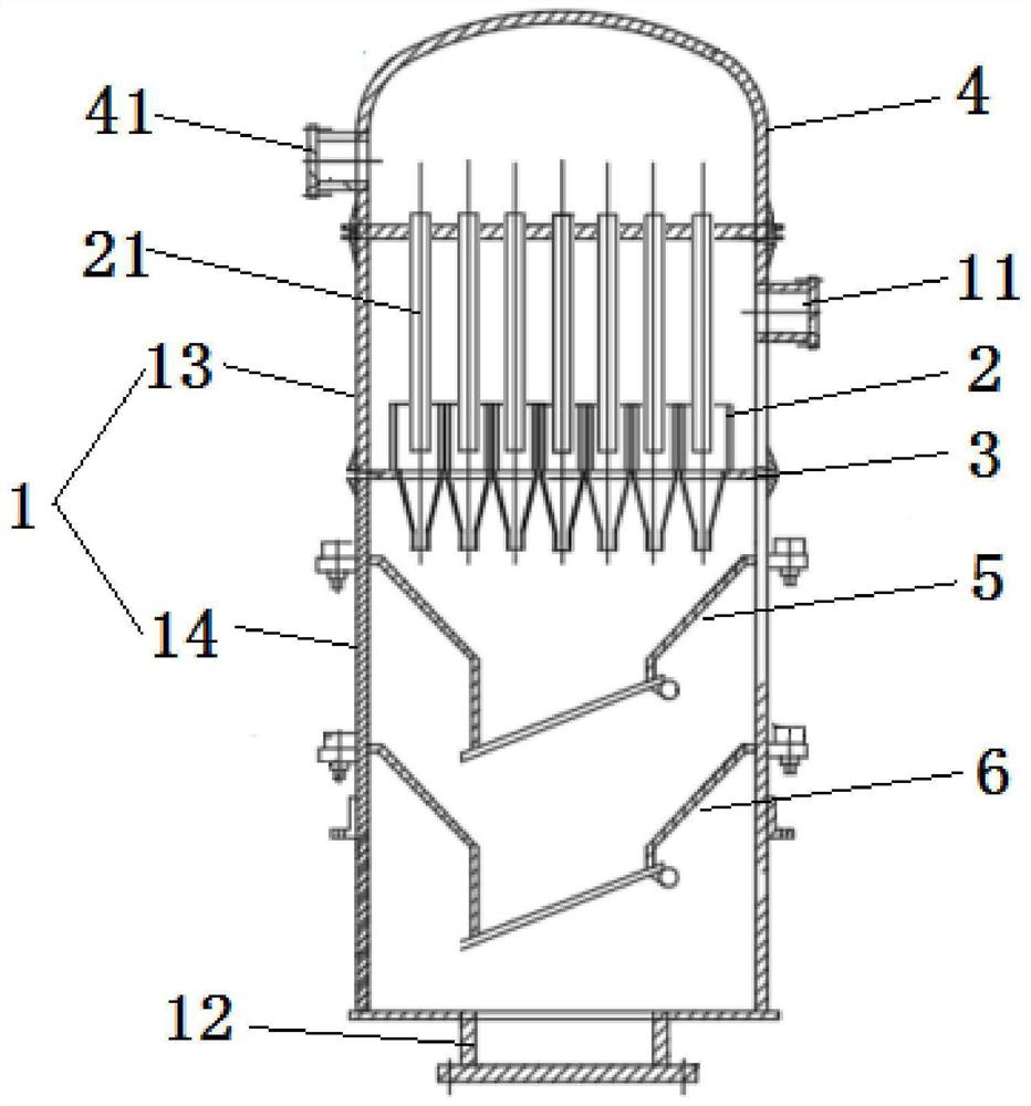
[0022] The following is attached figure 1 The principles and features of the present invention are described, and the examples given are only used to explain the present invention, and are not used to limit the scope of the present invention. In the following paragraphs the invention is described more specifically by way of example with reference to the accompanying drawings. Advantages and features of the present invention will be apparent from the following description and claims. It should be noted that all the drawings are in a very simplified form and use imprecise scales, and are only used to facilitate and clearly assist the purpose of illustrating the embodiments of the present invention.

[0023] Unless otherwise defined, all technical and scientific terms used herein have the same meaning as commonly understood by one of ordinary skill in the technical field of the invention. The terms used herein in the description of the present invention are for the purpose of d...


PUM

PropertyMeasurementUnit
diameteraaaaaaaaaa

Abstract

The invention discloses a multi-tube cyclone dust removal device, which comprises a shell and a plurality of cyclone dust removers, a baffle plate is horizontally installed in the shell, a separationchamber is formed by the area, located above the baffle plate, of the shell, and an ash collection chamber is formed by the area, located below the baffle, of the shell. A main air inlet communicatedwith the interior of the separation chamber is formed in the shell, a dust outlet communicated with the interior of the dust collection chamber is formed in the lower end of the shell, and the cyclonedust collectors are vertically installed at the upper ends of the baffle plates respectively. Air outlets in the upper ends of the cyclone dust removers communicate with the exterior of the shell through exhaust pipelines correspondingly, and the lower ends of the cyclone dust removers penetrate through the baffle plate correspondingly, so that dust discharging openings of the cyclone dust removers communicate with the interior of the dust collecting chamber correspondingly. The multi-tube cyclone dust removal device is large in treatment capacity, high in treatment precision and high in dustremoval efficiency.

Description

technical field [0001] The invention relates to the technical field of cyclone dust removal devices, in particular to a multi-pipe cyclone dust removal device. Background technique [0002] my country is rich in resources, oilfield mining technology is developed, mineral production is abundant, and there are many mines. When the wind speed is low in the narrow and long area of ​​the underground roadway, dust will accumulate in the local roadway. Most of them have a separation diameter of less than 70 μm and a median diameter of about 17 μm. About 30% are respirable dust. Workers technically wear dust masks that have the ability to absorb dust, but dust less than 10 μm is still in contact with the human body, and the dust further enters the respiratory system and digestive system through the nasal cavity or mouth, which will cause different degrees of harm to the human body. Direct contact with the skin will also cause certain damage, and the dust in the air will also cause h...

Claims


Application Information

Patent Timeline
Patent Type & Authority Applications(China)
IPC IPC(8): B01D45/16
CPCB01D45/16
Inventor 汪威张思奥林纬彭康郑小涛徐建民喻九阳
Owner WUHAN INSTITUTE OF TECHNOLOGY
Why Eureka
Try Eureka