
Monitoring camera power supply system based on solar energy

A technology for monitoring cameras and power supply systems. It is applied to the components of TV systems, TVs, and current collectors. It can solve problems such as unfavorable energy saving, slow switching response, and long interruption of camera power supply, so as to ensure stability and continuity. sexual effect

Active Publication Date: 2021-01-01
王军库
View PDF7 Cites 0 Cited by
  • Summary
  • Abstract
  • Description
  • Claims
  • Application Information

AI Technical Summary

Problems solved by technology

[0002] As a kind of image acquisition equipment, the camera is widely used in the current production and life to provide guarantee for the safety of people's production and life, and provide data support for security. Therefore, the working stability of the camera is extremely important, and the working stability of the camera Performance depends on two aspects: on the one hand, the working stability of the camera itself, and on the other hand, the power supply stability of the camera; The stability mainly depends on the stability of the power supply. In the prior art, the power supply of the camera generally adopts the mains power supply. The way of joint power supply, however, the existing circuit structure is complex, and the switching response between solar energy and mains power is slow, resulting in a long interruption of the power supply of the camera, which is not conducive to the collection of security data

Method used


Image

  • Monitoring camera power supply system based on solar energy
  • Monitoring camera power supply system based on solar energy
  • Monitoring camera power supply system based on solar energy

Examples


Embodiment Construction

[0029] The present invention will be further explained in detail below in conjunction with the accompanying drawings. It should be pointed out that the present invention is described in detail below only with preferred embodiments. , are all included in the scope of protection claimed by the technical solution of the present application.

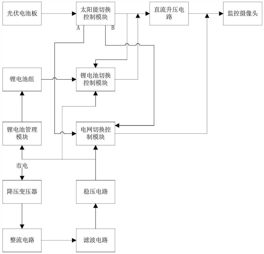
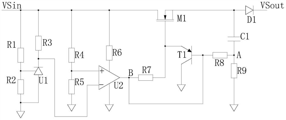
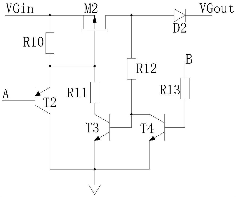
[0030] A monitoring camera power supply system based on solar energy provided by the present invention is characterized in that it includes a solar panel, a lithium battery management module, a lithium battery pack, a DC boost module, a grid power supply module, a solar switching control module, and a lithium battery switching control module. module and grid switching control module;

[0031] The output terminal of the solar panel is connected to the input terminal VSin of the solar switching control module, and the output terminal VSout of the solar switching control module is connected to the input terminal of the DC boost module;

[0032...


PUM


Abstract

The invention provides a monitoring camera power supply system based on solar energy. The monitoring camera power supply system comprises a solar cell panel, a lithium battery management module, a lithium battery pack, a direct-current boosting module, a power grid power supply module, a solar switching control module, a lithium battery switching control module and a power grid switching control module. The input end of the lithium battery management module is connected to the output end of the power grid power supply module, the output end of the lithium battery management module is connectedwith the positive electrode of the lithium battery pack, the positive electrode of the lithium battery pack is connected with the input end of the lithium battery switching control module, and the output end of the lithium battery switching control module is connected to the input end of the direct-current boosting module. The first detection input end of the lithium battery switching control module is connected to the output end of the power grid power supply module, and the second detection input end is connected to the output end of the solar switching control module; the power grid switching control module converts commercial power into direct current, the output end of the power grid switching control module is connected with the input end of the power grid switching control module,and the output end of the power grid switching control module supplies power to the camera.

Description

technical field [0001] The invention relates to a power supply system, in particular to a solar energy-based surveillance camera power supply system. Background technique [0002] As a kind of image acquisition equipment, the camera is widely used in the current production and life to provide guarantee for the safety of people's production and life, and provide data support for security. Therefore, the working stability of the camera is extremely important, and the working stability of the camera Performance depends on two aspects: on the one hand, the working stability of the camera itself, and on the other hand, the power supply stability of the camera; The stability mainly depends on the stability of the power supply. In the prior art, the power supply of the camera generally adopts the mains power supply. The joint power supply method, however, the existing circuit structure is complicated, and the switching response between solar energy and mains power is slow, which c...

Claims


Application Information

Patent Timeline
IPC IPC(8): H02J3/00H02J7/35H04N5/63
CPCH02J3/0073H02J7/35H04N5/63
Inventor 王军库
Owner 王军库
Learn More