
Clamping device

一种夹持装置、夹持件的技术,应用在夹钳、摩擦夹紧的可卸紧固件、连接构件等方向,能够解决无法快速完成夹持与拆卸、夹持力道不平均、夹持力道小等问题

Inactive Publication Date: 2020-12-29
PEGATRON
View PDF8 Cites 1 Cited by
  • Summary
  • Abstract
  • Description
  • Claims
  • Application Information

AI Technical Summary

Problems solved by technology

[0003] However, in the above methods, the advantage of using the elastic sheet method is that it can be quickly clamped, but the disadvantage is that the clamping force is relatively small and the clamping force is uneven
The screw locking method is the opposite. In order to share the clamping force evenly, four screws are used for locking. Therefore, the advantage is that the clamping force is relatively strong, and the object can be clamped reliably, but the disadvantage is that it will be more troublesome when locking. Clamping and dismounting cannot be completed quickly

Method used


Image

  • Clamping device
  • Clamping device
  • Clamping device

Examples


Embodiment Construction

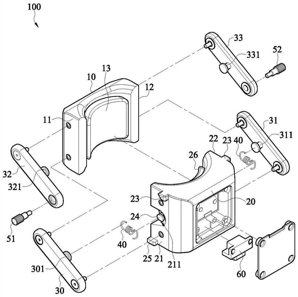
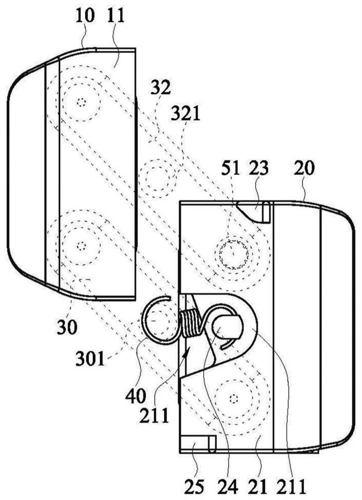
[0048] Please see first figure 1 and figure 2 , figure 1 is a perspective view of a clamping device according to an embodiment of the present disclosure, figure 2 is an exploded view of a clamping device according to an embodiment of the present disclosure, image 3 Is a side partial perspective view of a clamping device according to an embodiment of the present disclosure. The clamping device 100 of this embodiment includes a first clamping member 10 , a second clamping member 20 , a first connecting rod 30 , a second connecting rod 31 , a third connecting rod 32 , a fourth connecting rod 33 and an elastic member 40 . In other embodiments, only the first connecting rod 30 and the second connecting rod 31 may be provided, and the third connecting rod 32 and the fourth connecting rod 33 may be omitted, and the clamping effect can also be achieved, which will be described in detail later.

[0049] Depend on figure 1 and figure 2 It can be seen that the first clip 10 in...


PUM


Abstract

A clamping device includes a first clamping member, a second clamping member, a first connecting rod, a second connecting rod, and an elastic member. The first clamping member includes a first side and a second side opposite to each other. The second clamping member includes a third side and a fourth side opposite to each other. The first connecting rod is pivotally disposed between the first sideand the third side. The second connecting rod is pivotally disposed between the second side and the fourth side. The elastic member is connected between the third side and the first connecting rod. The elastic member provides a restoring force to make the first connecting rod rotate relative to the second clamping member, to drive the second connecting rod and the first clamping member to rotate,so that a distance between the first clamping member and the second clamping member is shortened to clamp an object.

Description

technical field [0001] The disclosure relates to a clamping device, which can be quickly assembled to an object and clamped and fixed. Background technique [0002] When it is necessary to clamp sensors or other objects to objects, clamps are usually used for fast assembly and disassembly. In the existing design, the clamp is usually combined by two clamps through bearings, and the clamping force is obtained by the return characteristics of torsion springs or shrapnel. For situations that require greater locking force, screws are generally used to strengthen the locking, for example, two clamping pieces are formed at the junction with the object to clamp the object to be clamped in it, and then four The corners are locked with screws, so that the two clamping pieces can firmly clamp the object under the action of the locking screws at the four corners. [0003] However, in the above-mentioned method, the advantage of using the elastic plate locking method is that it can be...

Claims


Application Information

Patent Timeline
Patent Type & Authority Applications(China)
IPC IPC(8): F16B2/18F16M13/02
CPCF16B2/185F16M13/022F16B2/06F16C11/04F16B5/02B25B5/04B25B5/108B25B5/14B25B5/163
Inventor 叶俊良徐国容
Owner PEGATRON
Learn More