
Wire winding device for optical fiber production

A technology for coiling and optical fibers, applied in the field of coiling devices for optical fiber production, can solve the problems of reduced production efficiency, increased labor intensity of workers, looseness, etc., and achieves the effect of improving work efficiency, reducing labor intensity, and improving winding quality.

Inactive Publication Date: 2020-12-29
湖南中科光电有限公司
View PDF10 Cites 0 Cited by
  • Summary
  • Abstract
  • Description
  • Claims
  • Application Information

AI Technical Summary

Problems solved by technology

[0003] In the process of optical fiber processing, it is generally necessary to wind and place the optical fiber after processing and manufacturing. In the production of some small and medium-sized enterprises, for small batch production, the optical fiber is often wound manually. Although this method reduces the However, the labor intensity of the workers is often greatly increased, and the work efficiency of the workers is low, which reduces the production efficiency. Therefore, a coil that can be used for winding optical fibers in small batches of small and medium-sized enterprises is needed. In addition, although there are some winding devices on the market that can wind optical fibers, these winding devices are often driven by motors to rotate the winding rollers, and then wind the optical fibers. This way makes the optical fibers wound in After winding on the roller, there may be loose phenomenon, which will affect the winding quality of the optical fiber

Method used


Image

  • Wire winding device for optical fiber production
  • Wire winding device for optical fiber production

Examples


Embodiment

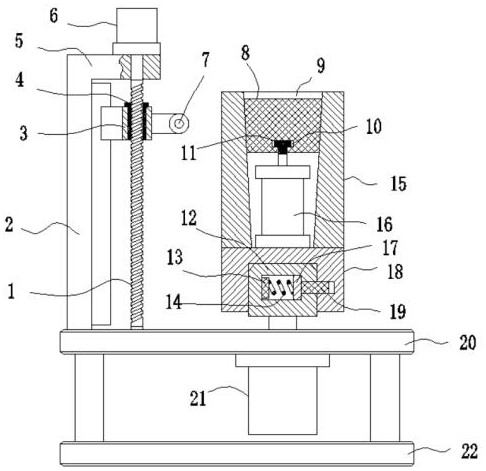
[0028] Such as Figure 1-2 As shown, a coiling device for optical fiber production includes:

[0029] bottom plate 22;

[0030] Mounting plate 20, described mounting plate 20 is horizontally arranged on the top of base plate 22 by installing a plurality of uprights;

[0031] Winding driving motor 21, described winding driving motor 21 is vertically installed on the mounting plate 20;

[0032] Turning seat 18, described turning seat 18 is driven and connected on the winding drive motor 21;

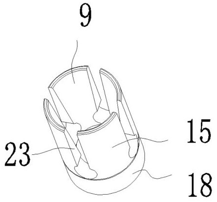
[0033] Collet 15, said collet 15 is coaxially arranged on the top of rotating seat 18, and conical groove 9 in the form of a through hole is coaxially provided on it, and the diameter of said conical groove 9 decreases successively from top to bottom, and said The circumferential surface of the collet 15 is provided with a plurality of strip-shaped notches 23 connecting the conical groove 9 along its axial array;

[0034] Wedge 8, the wedge 8 is a conical structure, and its shape is ada...


PUM


Abstract

The invention discloses a wire winding device for optical fiber production. The wire winding device comprises a bottom plate, a mounting plate, a winding driving motor, a rotating base, an elastic chuck, a conical groove, a strip-shaped notch, a wedge block and a lifting cylinder, wherein the lifting cylinder drives the wedge block to slide in the conical groove and drives the elastic chuck to generate deformation of elastically expanding towards the radial outer side of the elastic chuck. The wire winding device has the beneficial effects that the winding driving motor drives the rotating base to rotate to enable the elastic chuck to rotate, then an optical fiber can be wound on the elastic chuck, the labor intensity of workers is reduced, the working efficiency is improved, the lifting air cylinder drives the wedge block to move downwards, the wedge block slides in the conical groove of the elastic chuck, in the sliding process, the wedge block has radial inner side acting force on the inner wall of the conical groove, so that the elastic chuck generates elastic expansion deformation towards the radial outer side of the elastic chuck, the optical fiber wound around the elastic chuck can be expanded, the optical fiber is prevented from loosening after being wound around the elastic chuck, and the winding quality of the optical fiber is further improved.

Description

technical field [0001] The invention relates to the field of coiling equipment, in particular to a coiling device for optical fiber production. Background technique [0002] Optical fiber, short for optical fiber, is a fiber made of glass or plastic that acts as a means of light transmission. The transmission principle is "total reflection of light". A tiny optical fiber is encapsulated in a plastic sheath that allows it to be bent without breaking; typically, a transmitting device at one end of the fiber uses a light-emitting diode or a laser to send pulses of light into the fiber, and a receiving device at the other end of the fiber uses a photosensitive sensor. Component detection pulse. [0003] In the process of optical fiber processing, it is generally necessary to wind and place the optical fiber after processing and manufacturing. In the production of some small and medium-sized enterprises, for small batch production, the optical fiber is often wound manually. Alt...

Claims


Application Information

Patent Timeline
Patent Type & Authority Applications(China)
IPC IPC(8): B65H57/28B65H57/06B65H54/44B65H67/04
CPCB65H57/28B65H57/06B65H54/44B65H67/0411B65H2701/32
Inventor 卢立建
Owner 湖南中科光电有限公司
Learn More