Fuel cell flow field plate and fuel cell
A fuel cell and flow field plate technology, which is applied to fuel cells, fuel cell components, circuits, etc., can solve problems such as difficult processing, and achieve the effects of facilitating processing and manufacturing, promoting uniform distribution, and enhancing heat exchange capacity.
- Summary
- Abstract
- Description
- Claims
- Application Information
AI Technical Summary
Problems solved by technology
Method used
Image

Examples
Embodiment 1
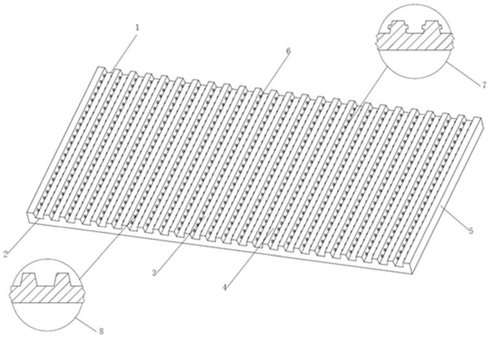
[0033] like figure 1 As shown, a fuel cell flow field plate provided by the present invention is mainly suitable for hydrogen-air fuel cells and hydrogen-oxygen fuel cells. The flow field plate is made of graphite material and includes an air inlet, an air outlet, and a flow channels, ridges and bosses on either side of the channel. The air inlet and the air outlet are connected through flow channels on the flow field plate. The flow channel adopts parallel flow channel, the cross section of the flow channel adopts trapezoidal cross section, and the ridges on both sides of the flow channel are evenly distributed with triangular bosses. The size and spacing of the bosses are unchanged. When the flow field plate of the present invention is in operation, the gas is passed into the inlet 1, the gas moves and reacts along the flow channel 3, and reaches the gas outlet 2 to discharge unreacted gas and water generated by reaction. The 4 in the flow field plate 5 are ridges, and th...
Embodiment 2
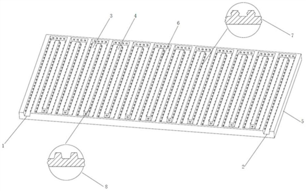
[0035] like figure 2 As shown, a fuel cell flow field plate provided by the present invention is mainly suitable for hydrogen-air fuel cells and hydrogen-oxygen fuel cells. The flow field plate is made of graphite material and includes an air inlet, an air outlet, and a flow channels, ridges and bosses on either side of the channel. The air inlet and the air outlet are connected through flow channels on the flow field plate. The flow channel adopts a serpentine flow channel, the cross section of the flow channel adopts a trapezoidal cross section, and rectangular bosses are evenly distributed on the ridges on both sides of the flow channel. The size and spacing of the bosses are unchanged. When the flow field plate of the present invention is in operation, the gas is passed into the inlet 1, the gas moves and reacts along the flow channel 3, and reaches the gas outlet 2 to discharge unreacted gas and water generated by reaction. The 4 in the flow field plate 5 are ridges, ...
Embodiment 3
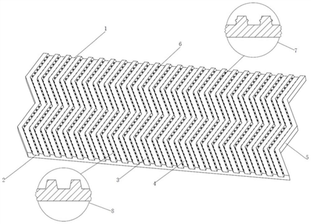
[0037] like image 3 As shown, a fuel cell flow field plate provided by the present invention is mainly suitable for hydrogen-air fuel cells and hydrogen-oxygen fuel cells. The flow field plate is made of metal materials, including an air inlet, an air outlet, and a flow channels, ridges and bosses on either side of the channel. The air inlet and the air outlet are connected through flow channels on the flow field plate. The flow channel adopts a folded flow channel, the cross section of the flow channel adopts a trapezoidal cross section, and semicircular bosses are evenly distributed on the ridges on both sides of the flow channel. The size and spacing of the bosses are unchanged. When the flow field plate of the present invention is in operation, the gas is passed into the inlet 1, the gas moves and reacts along the flow channel 3, and reaches the gas outlet 2 to discharge unreacted gas and water generated by reaction. The 4 in the flow field plate 5 are ridges, and the ...
PUM
 Abstract
Description
Claims
Application Information
 - R&D
- Intellectual Property
- Life Sciences
- Materials
- Tech Scout
- Unparalleled Data Quality
- Higher Quality Content
- 60% Fewer Hallucinations
Browse by: Latest US Patents, China's latest patents, Technical Efficacy Thesaurus, Application Domain, Technology Topic, Popular Technical Reports.
© 2025 PatSnap. All rights reserved.Legal|Privacy policy|Modern Slavery Act Transparency Statement|Sitemap|About US| Contact US: help@patsnap.com