
Three-support insulator fixing structure and GIL

A technology for supporting insulators and fixing structures. It is used in insulators, lead-in/through-type insulators, gas-filled/oil-filled cable accessories, etc. It can solve the problems of unfixed three-support insulators, easy deposition of fine dust particles, and impact on insulation performance. , to achieve the effect of simple and convenient fixed structure

Active Publication Date: 2020-12-25
HENAN PINGZHI HIGH VOLTAGE SWITCHGEAR +2
View PDF8 Cites 1 Cited by
  • Summary
  • Abstract
  • Description
  • Claims
  • Application Information

AI Technical Summary

Problems solved by technology

[0003] In the current GIL, the butt joint position of the two-section sealed cylinder is generally referred to the basin insulator in GIS, but the basin insulator is costly and heavy on the one hand; The basin-type insulator completely seals the joint position of the two sections of the sealed cylinder, and the dust particles in the vertical layout section are easily deposited in the concave space of the basin-type insulator, which will greatly improve the insulation performance at this position. big impact
Based on such problems, the idea of ​​arranging three-support insulators at the docking position of the two-segment sealing cylinders was proposed, but there is no suitable way to fix the three-supporting insulators at the docking positions of the two-segment sealing cylinders in the prior art fixed installation method

Method used


Image

  • Three-support insulator fixing structure and GIL
  • Three-support insulator fixing structure and GIL
  • Three-support insulator fixing structure and GIL

Examples


Embodiment Construction

[0039] In order to make the object, technical solution and advantages of the present invention more clear, the present invention will be further described in detail below in conjunction with the accompanying drawings and embodiments. It should be understood that the specific embodiments described here are only used to explain the present invention, and are not intended to limit the present invention, that is, the described embodiments are only some of the embodiments of the present invention, but not all of the embodiments. The components of the embodiments of the invention generally described and illustrated in the figures herein may be arranged and designed in a variety of different configurations.

[0040] Accordingly, the following detailed description of the embodiments of the invention provided in the accompanying drawings is not intended to limit the scope of the claimed invention, but merely represents selected embodiments of the invention. Based on the embodiments of ...


PUM


Abstract

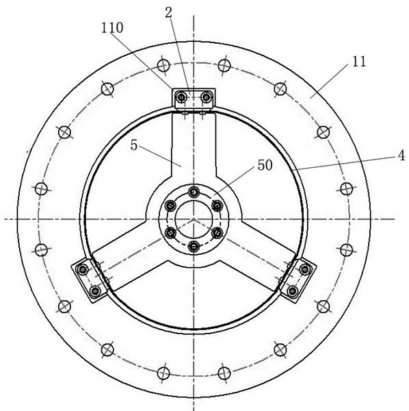
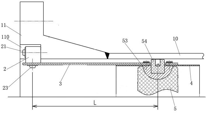
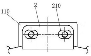
The invention relates to a three-support insulator fixing structure and a GIL. The three-support insulator fixing structure comprises a sealing cylinder, wherein the end part of the sealing cylinder is provided with a butt flange which is in sealed butt joint with an adjacent sealing cylinder; a receding groove which is formed in the inner edge of the butt flange and communicates with an inner cavity of the sealing cylinder; three supporting insulators which are located at the position, close to the butt flange, in the sealing cylinder; a connecting plate section which extends in the axial direction of the sealing cylinder; and a switching structure which is fixedly connected with the inner wall of the receding groove, wherein the inner end of the connecting plate section is fixedly connected with the support of the three support insulators, and the outer end is fixedly connected with the switching structure. By adopting the three-support insulator fixing structure provided by the invention, the three-support insulator and the sealing barrel body can be conveniently and fixedly connected through the connecting plate section and the switching structure, and when two adjacent sections of sealing barrel bodies are butted, the butting is not interfered through the avoidance of the receding groove; and fixed installation of the three-support insulator at the butt joint position of the two sections of sealed cylinder bodies is simply and conveniently realized.

Description

technical field [0001] The invention relates to the field of metal-enclosed gas-insulated transmission lines, in particular to a three-support insulator fixing structure and a GIL. Background technique [0002] At present, most of my country's energy bases are far away from load centers. How to scientifically solve the problem of large-capacity remote power transmission channels is one of the major issues facing power development. Due to the increasing scarcity of land resources, coupled with the huge pressure from ecological environment protection and the space constraints of special geographical areas, traditional power transmission channels dominated by overhead transmission lines are facing severe challenges. The electrical characteristics of GIL are similar to those of overhead transmission lines. It occupies a small space in the transmission corridor and does not generate harmful electromagnetic environment to the outside. At the same time, its operation is not affecte...

Claims


Application Information

Patent Timeline
IPC IPC(8): H01B17/30H01B17/38H02G15/20
CPCH01B17/301H01B17/38H02G15/20
Inventor 张垒苏戈李要锋赵艳涛勾国营张路阳龚咪咪戴本圣刘分马志强史春玲胡天宝彭崇陈会龙
Owner HENAN PINGZHI HIGH VOLTAGE SWITCHGEAR
Learn More