Full-automatic beer bottle capping device and using method thereof
A fully automatic technology for beer bottles, applied in the field of automatic capping devices for beer bottles, can solve the problems of untimely feeding of bottle caps, affecting the overall speed of the assembly line, etc.
- Summary
- Abstract
- Description
- Claims
- Application Information
AI Technical Summary
Problems solved by technology
Method used
Image

Examples
Embodiment 1
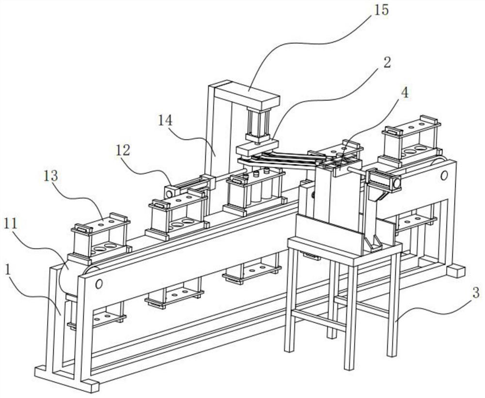
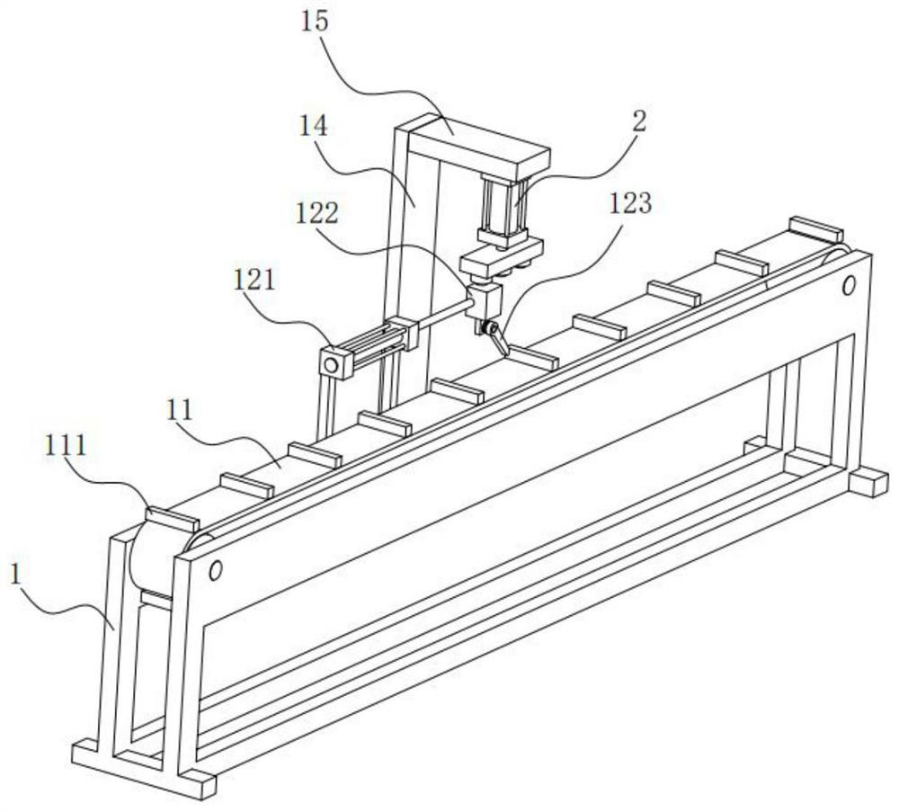
[0041] Embodiment one: if Figure 1-6 As shown, a beer bottle automatic capping device includes a transmission frame 1, on which a transmission belt 11 and a driving mechanism 12 for driving the transmission belt 11 are arranged, and on the transmission belt 11 are provided with multiple groups for A placement mechanism 13 for placing beer bottles, one side of the transmission frame 1 is vertically provided with a vertical support seat 14, the top of the vertical support seat 14 is provided with a horizontal support seat 15, and the bottom surface of the horizontal support seat 15 is provided with a capping mechanism 2 , the capping mechanism 2 is located directly above the conveyor belt 11, the capping mechanism 2 includes a press-down cylinder 21, the cylinder barrel of the press-down cylinder 21 is fixedly arranged on the transverse support seat 15, and the piston rod of the press-down cylinder 21 is provided with a The pressure plate 22, the side of the lower pressure plat...
Embodiment 2
[0054] Embodiment two: if Figure 7-8 As shown, a fully automatic beer bottle capping device, the difference between this embodiment and Embodiment 1 is that: in this embodiment, the suction cap assembly 23 includes a plurality of disc-shaped blocks 231, and a plurality of disc-shaped blocks 231 They are all welded on the lower pressing plate 22 and evenly distributed along the length direction of the lower pressing plate 22. There is a mounting groove in the disc-shaped block 231, and a powerful magnet block 232 is embedded in the mounting groove. The accommodation groove 233 of the cap, the diameter of the accommodation groove 233 is greater than the diameter of the installation groove and communicates with the installation groove. The lower bottle cap will be absorbed into the holding groove 233, because the diameter of the holding groove 233 is greater than the diameter of the installation groove, the bottle cap will not collide with the powerful magnet block 232, but will...
Embodiment 3
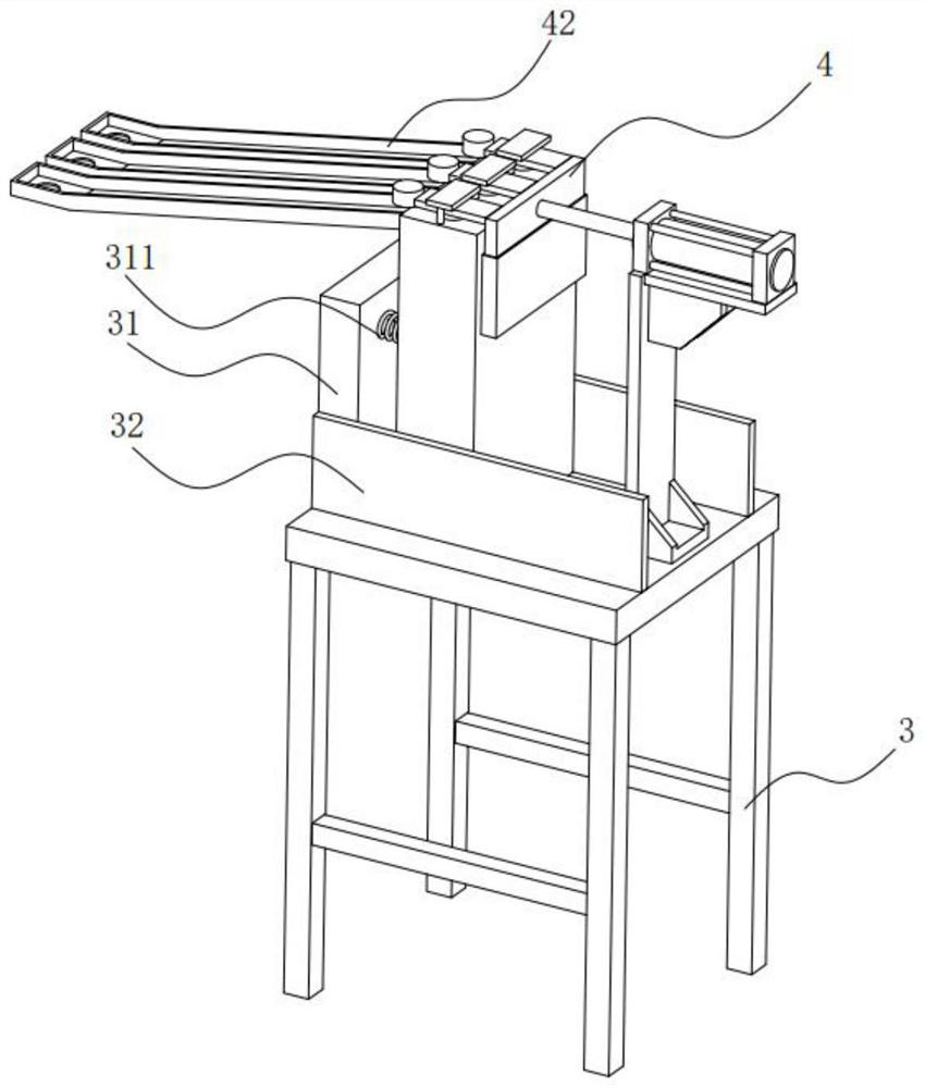
[0055] Embodiment three: as Figure 9-10 As shown, a fully automatic capping device for beer bottles. The difference between this embodiment and Embodiment 1 is that the placement mechanism 13 includes a placement seat 131, which is a strip-shaped seat, and the placement seat 131 is distributed along its own length direction. There are a plurality of placement grooves 1311 for placing beer bottles, both ends of the placement seat 131 are provided with support plates 132, and a pressing plate 133 is arranged above the placement seat 131, and a bottle for beer bottles is provided on the pressing plate 133. The through hole 1331 through which the mouth passes, the two ends of the pressing plate 133 are provided with slide grooves and are slidably arranged on the supporting plate 132, the supporting plate 132 is provided with a positioning piece 134 for fixing the position of the pressing plate 133, and the positioning piece 134 Including a positioning block 1341 and a positioning...
PUM
 Abstract
Description
Claims
Application Information
 - R&D
- Intellectual Property
- Life Sciences
- Materials
- Tech Scout
- Unparalleled Data Quality
- Higher Quality Content
- 60% Fewer Hallucinations
Browse by: Latest US Patents, China's latest patents, Technical Efficacy Thesaurus, Application Domain, Technology Topic, Popular Technical Reports.
© 2025 PatSnap. All rights reserved.Legal|Privacy policy|Modern Slavery Act Transparency Statement|Sitemap|About US| Contact US: help@patsnap.com