Roller chain assembling and positioning clamp

A technology for positioning fixtures and chains, which is applied in the direction of manufacturing tools, workpiece clamping devices, etc., can solve the problems that the precision of sleeves and inner chains cannot be guaranteed, and the batch processing of roller chains is unfavorable, so as to improve processing efficiency and improve Yield rate, effect of improving machining accuracy

Active Publication Date: 2020-12-25
溧阳市超强链条制造有限公司
View PDF12 Cites 0 Cited by
  • Summary
  • Abstract
  • Description
  • Claims
  • Application Information

AI Technical Summary

Problems solved by technology

[0003] During the assembly process of the roller chain, several sleeves, rollers and inner chain pieces need to be combined into a whole, and several assembled rollers are connected to each other through the outer chain piece and the pin shaft to form a chain. Some roller chains are mostly manually operated by pressing equipment to press the rollers, sleeves and inner chains together, and the sleeves, rollers and inner chains need to be manually inserted into each other in sequence. The method cannot guarantee the precision between the sleeve and the inner chain piece during pressing, and at the same time, only one set of sleeves, rollers and inner chain pieces can be pressed together, which is not conducive to the batch processing of roller chains

Method used


Image

  • Roller chain assembling and positioning clamp
  • Roller chain assembling and positioning clamp
  • Roller chain assembling and positioning clamp

Examples


Embodiment Construction

[0024] In order to make the technical means, creative features, goals and effects achieved by the present invention easy to understand, the present invention will be further described below in conjunction with specific illustrations. It should be noted that, in the case of no conflict, the embodiments in the present application and the features in the embodiments can be combined with each other.

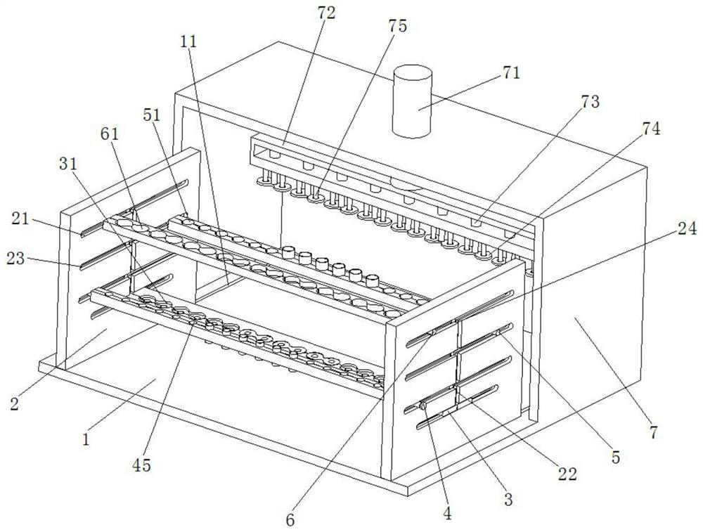
[0025] Such as Figure 1 to Figure 6 As shown, a roller chain assembly and positioning fixture includes a base 1 and a positioning frame 2. The base 1 is symmetrically provided with a No. 1 chute 11, and the bottom of the positioning frame 2 is inserted in the No. 1 chute 11 and slidably connected. The locating frame 2 is provided with some moving grooves 21 symmetrically and horizontally. The locating frame 2 is provided with vertical grooves 22 symmetrically and vertically. There are No. 2 chute 23 and No. 3 chute 24. The No. 2 chute 23 is connected with the symmetrically arranged...


PUM


Abstract

The invention relates to the field of chain processing, in particular to a roller chain assembling and positioning clamp. The roller chain assembling and positioning clamp comprises a base and a positioning frame, wherein first sliding grooves are symmetrically formed in the base, and the bottom of the positioning frame is inserted into the first sliding grooves and connected with the first sliding grooves in a sliding manner; a plurality of moving grooves are symmetrically and horizontally formed in the positioning frame, and vertical grooves are symmetrically and vertically formed in the positioning frame; the vertical grooves and the moving grooves are arranged in a longitude and latitude interweaving manner and communicate with each other; second sliding grooves are formed in the moving grooves separately, third sliding grooves are formed in the vertical grooves separately, and the second sliding grooves communicate with the corresponding third sliding grooves which are symmetrically formed; a bottom plate is symmetrically inserted into the bottoms of two moving grooves, and two ends of the bottom plate are inserted into two second sliding grooves; a plurality of inserting grooves with arc-shaped structures are symmetrically formed in the top of the bottom plate, and every two inserting grooves are symmetrically formed; and a first support is symmetrically inserted into another two moving grooves and located above the bottom plate. All components of a roller chain can be spliced in a high-precision manner, and the roller chain assembling and positioning clamp is suitable for popularization.

Description

technical field [0001] The invention relates to the field of chain processing, in particular to a roller chain assembling and positioning fixture. Background technique [0002] Roller chain is a type of power chain used in conveying machinery, widely used in household, industrial and agricultural machinery, including conveyors, plotters, printing machines, automobiles, motorcycles, and bicycles. It consists of a series of short cylindrical rollers linked together and driven by a gear called a sprocket, which is a simple, reliable and efficient power transmission device. [0003] During the assembly process of the roller chain, several sleeves, rollers and inner chain pieces need to be combined into a whole, and several assembled rollers are connected to each other through the outer chain piece and the pin shaft to form a chain. Some roller chains are mostly manually operated by pressing equipment to press the rollers, sleeves and inner chains together, and the sleeves, roll...

Claims


Application Information

Patent Timeline
Patent Type & Authority Applications(China)
IPC IPC(8): B25B11/02
CPCB25B11/02
Inventor 蒋俊波蒋俊美毕永光蒋阿生
Owner 溧阳市超强链条制造有限公司
Why Eureka
Try Eureka