
An automatic chip removal device for CNC machine tools

A CNC machine tool and automatic row technology, which is applied in metal processing machinery parts, metal processing equipment, maintenance and safety accessories, etc., can solve the problems of operator hazards, waste of cutting fluid, and difficulty in cleaning, so as to reduce the difficulty of operation and reduce cleaning. Cost, effect of improving safety

Active Publication Date: 2022-03-04
LINYI ZHENGDA MACHINERY
View PDF0 Cites 0 Cited by
  • Summary
  • Abstract
  • Description
  • Claims
  • Application Information

AI Technical Summary

Problems solved by technology

[0003] First, in the process of CNC machine tool processing, the size of iron filings is different, and the force they are subjected to is also different, resulting in different falling trends. Some iron filings shoot around and fall on the machine tool, forming Accumulation affects processing, and it is not easy to clean, even some tiny iron filings are mixed into the air and discharged outward, which is likely to cause harm to the operator. Moreover, the iron filings falling on the machine tool are often flushed with a large flow of coolant, or using Compressed air blowing and other methods make the chips enter the chip flute, and then recover the cutting fluid and discharge the chips. Of these two methods, the former method will waste a lot of cutting fluid, resulting in increased cleaning costs. The latter method is harmful to iron The scraps are blown to make the scraps fly and mix with the air, further increasing the hazards to the operators

Method used


Image

  • An automatic chip removal device for CNC machine tools
  • An automatic chip removal device for CNC machine tools
  • An automatic chip removal device for CNC machine tools

Examples


Embodiment Construction

[0018] The following will clearly and completely describe the technical solutions in the embodiments of the present invention with reference to the accompanying drawings in the embodiments of the present invention. Obviously, the described embodiments are only some, not all, embodiments of the present invention. Based on the embodiments of the present invention, all other embodiments obtained by persons of ordinary skill in the art without making creative efforts belong to the protection scope of the present invention.

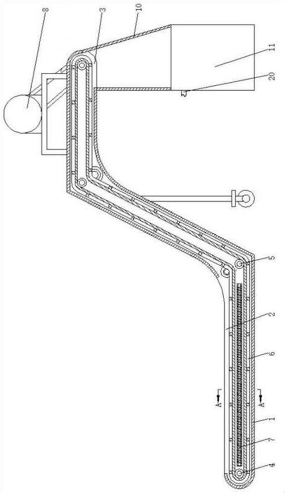
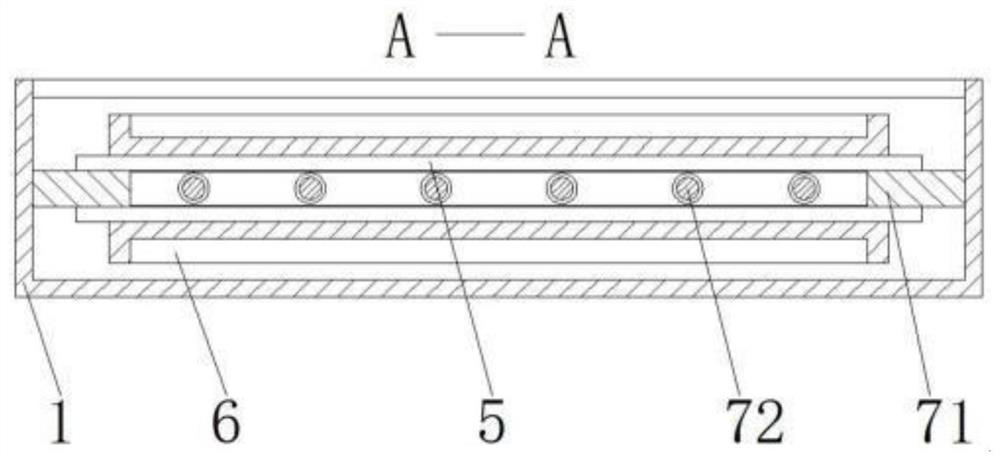
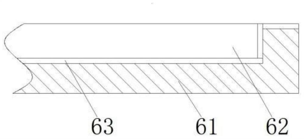
[0019] see Figure 1-4 , an automatic chip removal device for a CNC machine tool, comprising a fixed frame 1, a fixed frame 12 and a mechanical arm, the upper surface of the left part of the fixed frame 1 is provided with a chip drop port 2, and the bottom surface of the right part of the fixed frame 1 is provided with an outlet Chip mouth 3, the inside of both ends of the fixed frame-1 are respectively equipped with roller shafts 4, and the middle part of the...


PUM


Abstract

The invention relates to the technical field of numerically controlled machine tools, and discloses an automatic chip removal device for numerically controlled machine tools, which includes a fixed frame 1, a fixed frame 2 and a mechanical arm. The bottom surface of the right part of frame one is provided with a chip outlet, and roller shafts are respectively movably installed inside the two ends of the fixed frame one, and a steering guide roller is movably installed in the middle part of the fixed frame one, and the roller shaft is located on the fixed frame An inner movable socket has a transmission belt. Through the setting of the electromagnetic device 1, the electromagnetic device 1 forms a certain electromagnetic field under the machine tool, and changes the falling trend and direction of the iron filings, increasing the number of iron filings falling into the conveyor belt, thereby reducing the number of iron filings falling into the conveyor belt. The number of machine tools reduces the impact of excessive iron filings on processing. At the same time, the electromagnetic field formed by the electromagnetic device absorbs fine iron filings, reduces air pollution, and improves the safety of operators during CNC machine tool processing.

Description

technical field [0001] The invention relates to the technical field of numerical control machine tools, in particular to an automatic chip removal device for numerical control machine tools. Background technique [0002] The removal of chips is an important issue that must be considered in machining. This problem is more important for CNC machine tools. The processing efficiency of CNC machine tools is high. A large number of metal chips of CNC machine tools occupy the processing area per unit time. If they are not removed in time, It will inevitably cover or wrap on the workpiece, so that the automatic processing cannot continue, and the hot chips will also dissipate heat to the machine tool workpiece, causing thermal deformation of the machine tool or workpiece, affecting the machining accuracy. It is very important for CNC machine tool processing, and the main function of the chip removal device is to discharge chips from the processing area to the outside of the CNC mach...

Claims


Application Information

Patent Timeline
Patent Type & Authority Patents(China)
IPC IPC(8): B23Q11/00
CPCB23Q11/0064
Inventor 姚琴琴
Owner LINYI ZHENGDA MACHINERY
Learn More