Eureka AIR delivers breakthrough ideas for toughest innovation challenges, trusted by R&D personnel around the world.

Chemical production gas transfer drying device

A drying device, chemical production technology, applied in gas treatment, chemical instruments and methods, separation of dispersed particles, etc., can solve problems such as single drying method, poor drying effect, affecting the quality of gas drying, etc., to achieve good drying effect, Effect of improving drying quality and drying efficiency

Inactive Publication Date: 2020-12-25
夏吾措吉
View PDF0 Cites 4 Cited by
  • Summary
  • Abstract
  • Description
  • Claims
  • Application Information

AI Technical Summary

Problems solved by technology

[0004] Based on the technical problems that the existing drying device has a simple design structure and a single drying method, which leads to poor drying effect and affects the drying quality of the gas, the present invention proposes a transfer drying device for chemical production gas

Method used


Image

  • Chemical production gas transfer drying device
  • Chemical production gas transfer drying device
  • Chemical production gas transfer drying device

Examples


Embodiment 1

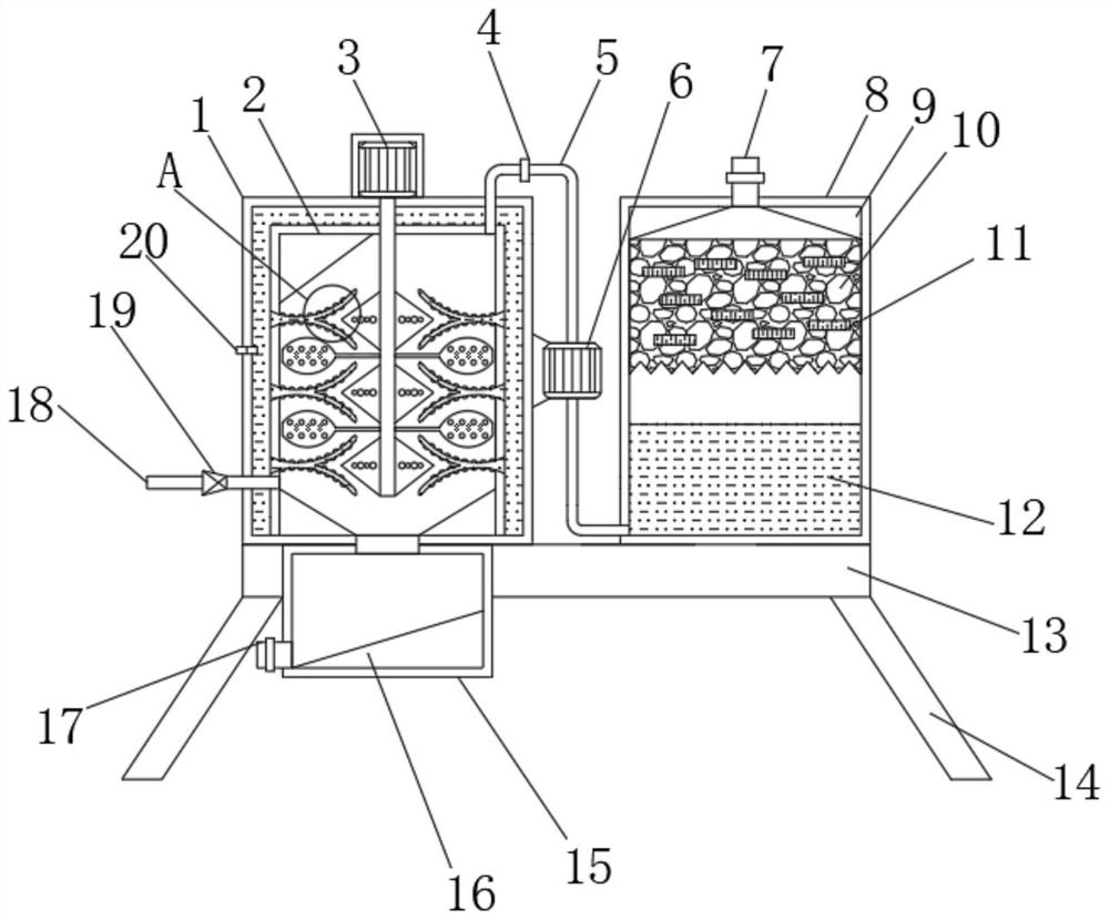
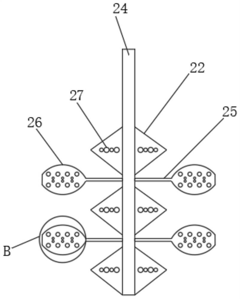
[0027] refer to Figure 1-5 , a chemical production gas transfer drying device, comprising a base 13, one side of the top outer wall of the base 13 is fixed with a first drying box 1 by screws, and the bottom inner wall of the first drying box 1 is provided with an inner cylinder 2, the first The gap between the drying box 1 and the inner cylinder 2 is provided with condensate, and the inner wall around the inner cylinder 2 is provided with through holes distributed equidistantly, and the inner wall of the through hole is inserted with a herringbone heat pipe 23, and the outer wall of the herringbone heat pipe 23 A heat conduction protrusion 21 is provided, and the top outer wall of the first drying box 1 is fixed with a motor 3 by screws, and the output shaft of the motor 3 is connected with a stirring mechanism through a coupling, and the other side of the top outer wall of the base 13 is fixed with a screw. The second drying box 8, and the bottom inner wall of the second dr...

Embodiment 2

[0036] refer to figure 1 , a gas transfer drying device for chemical production. Compared with Embodiment 1, this embodiment also includes an installation hole on the other side of the outer wall of the first drying box 1, and a semiconductor refrigeration chip 20 is inserted into the inner wall of the installation hole.

[0037] The hot gas conducts continuous heat exchange through the herringbone heat pipe 23. During the heat exchange, the temperature of the condensate will gradually rise. Can affect the drying process of the gas.


PUM


Abstract

The invention belongs to the technical field of chemical production, and particularly relates to a chemical production gas transfer drying device. In order to solve the problems that an existing drying device is simple in design structure and single in drying mode, so that the drying effect is poor, and the drying quality of gas is affected, the device is provided. The device comprises a base, a first drying box is fixed to one side of the outer wall of the top of the base through screws, an inner barrel is arranged on the inner wall of the bottom of the first drying box, condensate is arranged in a gap between the first drying box and the inner barrel, through holes distributed at equal intervals are formed in the inner wall of the periphery of the inner barrel, and herringbone heat conduction pipes are inserted into the inner walls of the through holes. A draught fan can extract gas in the first drying box into a second drying box, the gas can be adsorbed by the concentrated sulfuricacid, a calcium oxide layer and a silica gel layer in the second drying box, and most of moisture in the gas can be removed, so the good drying effect is achieved, and the drying quality of the gas is improved.

Description

technical field [0001] The invention relates to the technical field of chemical production, in particular to a transfer drying device for chemical production gas. Background technique [0002] Chemical industry is the abbreviation of "chemical technology", "chemical industry", "chemical engineering", etc. Any technology that uses chemical methods to change the composition and structure of substances or synthesize new substances belongs to chemical production technology, that is, chemical technology. It is called chemicals or chemical products. At first, the production of such products was manual workshops, and later evolved into factories, and gradually formed a specific production industry, that is, the chemical industry. Chemical engineering is a discipline that studies the common laws of the production process of chemical products. science. [0003] In the process of chemical production, a lot of hot gas is often produced, and the humidity in the hot gas is generally rel...

Claims


Application Information

Patent Timeline
Patent Type & Authority Applications(China)
IPC IPC(8): B01D53/26
CPCB01D53/261B01D53/265B01D2257/80
Inventor 夏吾措吉
Owner 夏吾措吉
Why Eureka
Eureka Blog
Learn More