Spiral Lift Slipper Washing Rack
A technology of spiral lifting and cleaning racks, which is applied to the cleaning of boots and shoes, cleaning equipment, household cleaning devices, etc., can solve the problems of unstable cleaning quality and dead angles in the groove of the sole, and achieve the effect of ensuring quality and cleaning quality
- Summary
- Abstract
- Description
- Claims
- Application Information
AI Technical Summary
Problems solved by technology
Method used
Image
Examples
Embodiment 1
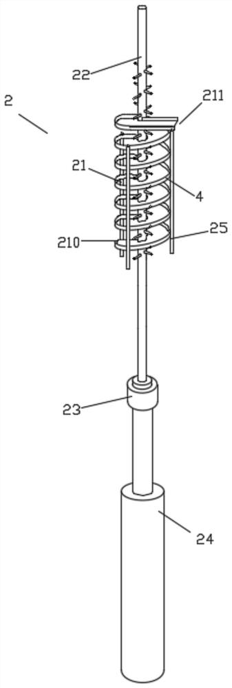
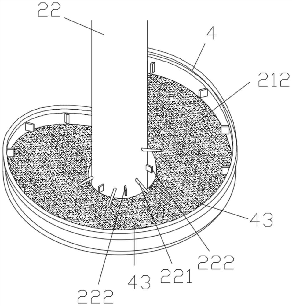
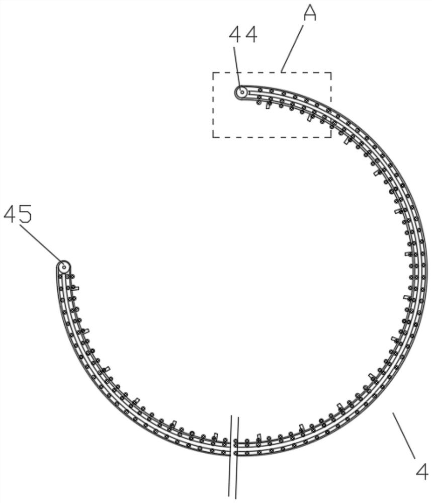
[0038] Such as figure 1 As shown, the spiral lifting type slippers cleaning rack 2 disclosed in this embodiment includes a spiral track 21 , a rotatable lifting center column 22 and a conveyor belt device 4 . At least three supporting frames are arranged on the outer periphery of the spiral track 21 for supporting the spiral track 21 to keep it stable. The bottom starting point of the helical track 21 can be used as its material inlet 210 , and the top dead center of the helical track 21 can be used as its material outlet 211 . The spiral track 21 is spirally arranged around the central column 22 , and the conveyor belt device 4 is spirally arranged along the outer edge of the spiral track 21 .
[0039] The central column 22 is driven by a rotary lift mechanism. Rotary lifting mechanism can select existing mechanism for use. In this embodiment, the rotary lifting mechanism includes a motor 23 and a linear drive mechanism 24 , the output end of the linear drive mechanism 24 ...
Embodiment 2
[0060] The difference between this embodiment and Embodiment 1 is that: Figure 10 , 11 As shown, the brushes in this embodiment include a fixed brush 212 and a rotating brush 215 that can rotate automatically. The fixed brush 212 is laid on the top surface of the spiral track 21, and the rotating brush 215 is arranged at intervals along the spiral track 21. The brush 212 is provided avoiding the rotating brush 215 . The rotating brush 215 is driven by a brush motor 216 . The rotating brush 215 in this embodiment can actively scrub the soles of the slippers 5, and the cleaning effect is better.
[0061] The sum of the diameters of the two rotating brushes 215 is preferably close to the width of the helical track 21, ensuring that almost the entire sole can be cleaned.
Embodiment 3
[0063] The difference between this embodiment and embodiment one or embodiment two is: as Figure 1-12 As shown, the present embodiment also includes a cabinet body 6, the cabinet body 6 has two upper and lower layers respectively, the spiral track 21 is installed on the upper layer of the cabinet body 6, and the rotating lifting mechanism of the central column 22 is installed on the lower layer of the cabinet body 6, between the upper and lower layers There are holes for the central column 22 to pass through. Some shower heads 62 are installed on the inner wall and the top of the upper space, which can flush the spiral track 21 from all around and above, so as to increase the cleaning effect.
[0064] There is a gap 61 at the position corresponding to the discharge port 211 on the cabinet body 6 , and the cleaned slippers can be transported to the outside of the cabinet body 6 through the gap 61 . Due to the long length of the central column 22 , the central column 22 in thi...
PUM
 Abstract
Description
Claims
Application Information
 - Generate Ideas
- Intellectual Property
- Life Sciences
- Materials
- Tech Scout
- Unparalleled Data Quality
- Higher Quality Content
- 60% Fewer Hallucinations
Browse by: Latest US Patents, China's latest patents, Technical Efficacy Thesaurus, Application Domain, Technology Topic, Popular Technical Reports.
© 2025 PatSnap. All rights reserved.Legal|Privacy policy|Modern Slavery Act Transparency Statement|Sitemap|About US| Contact US: help@patsnap.com


