


Quick Research
Generate reliable direction feasibility study reports for your R&D in just a few steps.

Technical Q&A
Discover and master advanced knowledge NOW. Basics, ideas, possibilities, all at once.

Find Solutions
As an expert in R&D theories, this can generate solutions to your technical problems instantly.

Evaluate Feasibility
Analyze your overall solution with one click, know your potential R&D risks in advance.

Monitor Landscape
Get weekly tech updates, stay abreast of the latest tech innovations and key insights.
Microwave plasma torch ignition method
A microwave plasma, microwave technology, applied in the direction of plasma, electrical components, etc.
- Summary
- Abstract
- Description
- Claims
- Application Information
AI Technical Summary
Problems solved by technology
Method used
Image

Examples
Embodiment 1
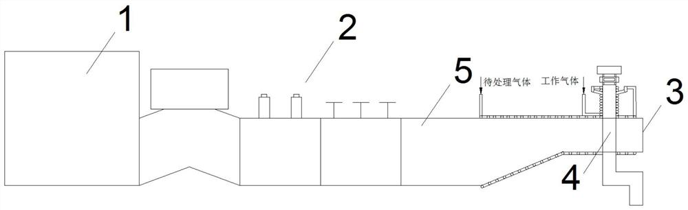
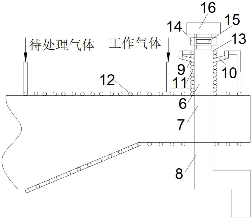
[0021] See attached Figure 1~2 . A microwave plasma torch ignition method, using a microwave plasma torch; the microwave plasma torch includes a microwave generator 1, a microwave delivery device 2, a shielding shell 3 and a discharge tube 4; the discharge tube 4 runs through the shielding shell 3; The shielding shell 3 is provided with a feed port; the feed port is used to receive the microwave input from the microwave generator 1 through the microwave delivery device 2; the discharge tube 4 is used to input the working gas and receive the microwave input from the feed port; The microwave generator 1 has at least a pulse wave mode of operation and a continuous wave mode of operation; comprising the following steps:
[0022] Step S10, inputting working gas into the discharge tube 4;
[0023] Step S20, the microwave generator 1 is turned on, and the working mode is set to the pulse wave working mode, and the microwave generator 1 inputs pulse waves to the working gas in the ...
Embodiment 2
[0027] See attached Figure 1~2 . A microwave plasma torch ignition method, using a microwave plasma torch; the microwave plasma torch includes a microwave generator 1, a microwave delivery device 2, a shielding shell 3 and a discharge tube 4; the discharge tube 4 runs through the shielding shell 3; The shielding shell 3 is provided with a feed port; the feed port is used to receive the microwave input from the microwave generator 1 through the microwave delivery device 2; the discharge tube 4 is used to input the working gas and receive the microwave input from the feed port; The microwave generator 1 has at least a pulse wave mode of operation and a continuous wave mode of operation; comprising the following steps:
[0028] Step S10, inputting working gas into the discharge tube 4;
[0029] Step S20, the microwave generator 1 is turned on, and the working mode is set to the pulse wave working mode, and the microwave generator 1 inputs pulse waves to the working gas in the ...
Embodiment 3
[0034] See attached Figure 1~2 . A microwave plasma torch ignition method, using a microwave plasma torch; the microwave plasma torch includes a microwave generator 1, a microwave delivery device 2, a shielding shell 3 and a discharge tube 4; the discharge tube 4 runs through the shielding shell 3; The shielding shell 3 is provided with a feed port; the feed port is used to receive the microwave input from the microwave generator 1 through the microwave delivery device 2; the discharge tube 4 is used to input the working gas and receive the microwave input from the feed port; The microwave generator 1 has at least a pulse wave mode of operation and a continuous wave mode of operation; comprising the following steps:
[0035] Step S10, inputting working gas into the discharge tube 4;
[0036] Step S20, the microwave generator 1 is turned on, and the working mode is set to the pulse wave working mode, and the microwave generator 1 inputs pulse waves to the working gas in the ...
PUM
 Abstract
Description
Claims
Application Information
 - R&D Engineer
- R&D Manager
- IP Professional
- Industry Leading Data Capabilities
- Powerful AI technology
- Patent DNA Extraction
Browse by: Latest US Patents, China's latest patents, Technical Efficacy Thesaurus, Application Domain, Technology Topic, Popular Technical Reports.
© 2024 PatSnap. All rights reserved.Legal|Privacy policy|Modern Slavery Act Transparency Statement|Sitemap|About US| Contact US: help@patsnap.com