Novel transformer protection control device

A technology of transformer protection and control device, applied in transformer/inductor cooling, transformer/inductor housing, transformer/inductor components, etc., can solve the problems of poor protection, high risk of fire extinguishing methods, cumbersome and time-consuming, etc. To achieve the effect of efficient, fast and comprehensive fire extinguishing, better heat dissipation effect, and ingenious and reasonable structure

Active Publication Date: 2020-12-18
江苏诺盛电气科技有限公司
View PDF3 Cites 1 Cited by
  • Summary
  • Abstract
  • Description
  • Claims
  • Application Information

AI Technical Summary

Problems solved by technology

[0004] 1. Part of the transformer is exposed and has a better heat dissipation effect, but it is not well protected in extreme weather such as heavy rain or snow, and is prone to failure and safety accidents;
[0005] 2. Some transformers are placed in the cabinet, but the heat dissipation effect becomes poor, and it is extremely inconvenient to disassemble the cabinet for maintenance, and it is not energy-saving and environmentally friendly;
[0006] 3. Some transformers need to manually clean litter, mosquito cobwebs or dust, etc., which is cumbersome and time-consuming, and there are potential safety hazards, which will affect the power supply of the line in a short time;
[0007] 4. The transformer lacks safety protection and control equipment, and it is difficult to extinguish the fire in time when encountering a fire, and the traditional fire extinguishing method is risky. When the general professional fire extinguishers arrive, the fire is already large

Method used


Image

  • Novel transformer protection control device
  • Novel transformer protection control device
  • Novel transformer protection control device

Examples


Embodiment Construction

[0029] In order to make the object, technical solution and advantages of the present invention clearer, the present invention will be further described in detail below in combination with specific embodiments and with reference to the accompanying drawings. It should be understood that these descriptions are exemplary only, and are not intended to limit the scope of the present invention. Also, in the following description, descriptions of well-known structures and techniques are omitted to avoid unnecessarily obscuring the concept of the present invention.

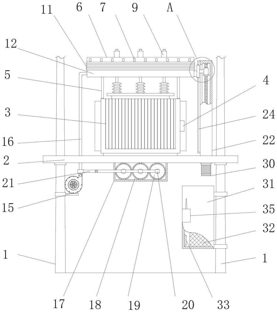
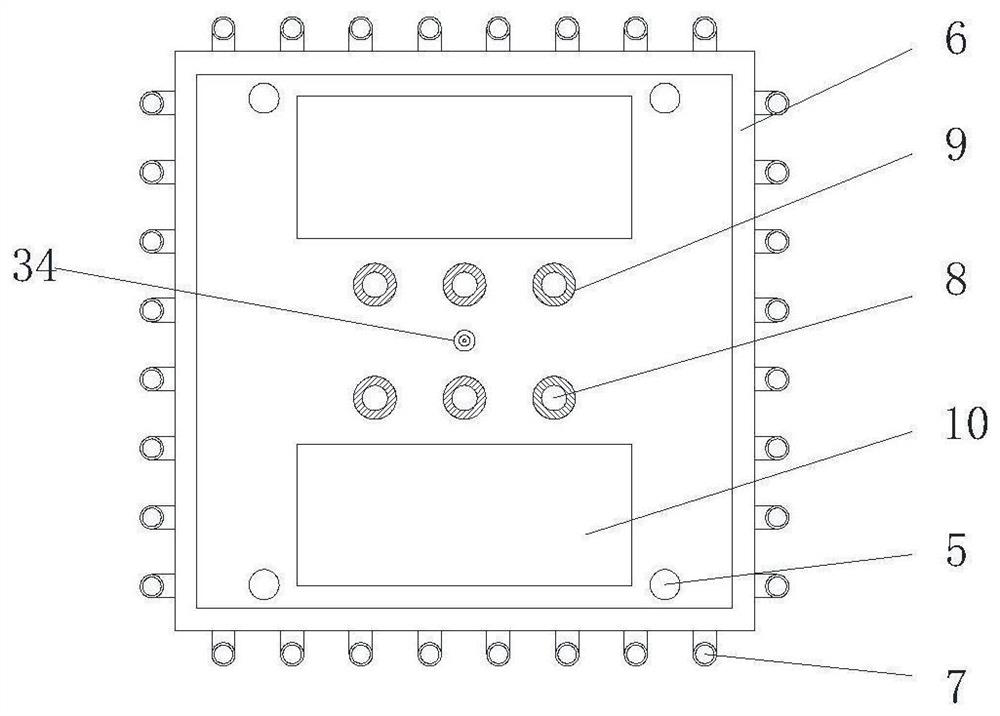
[0030] Such as Figure 1-6 As shown, a novel transformer protection control device proposed by the present invention includes a column group 1, a vertical slide plate 25 and a fire extinguishing module. The column group 1 includes a left column and a right column. Jointly supporting and connecting with the lower part of the right column, there is an installation base plate 2, and the upper end of the installation base pl...


PUM


Abstract

A novel transformer protection control device comprises a stand column set, a vertical sliding plate and a fire extinguishing module; wherein the stand column set comprises a left stand column and a right stand column, the lower portions of the left stand column and the right stand column are both buried in the ground, and the lower portions of the left stand column and the right stand column arejointly connected with an installation bottom plate in a supporting mode. Supporting columns are arranged on the left side and the right side of the upper end of the transformer body, and the upper ends of the supporting columns are jointly connected with a top cover in a supporting mode. Four-side air cooling can be carried out through the Y-shaped blowpipe, so that the coverage area is larger and the heat dissipation effect is better; the Y-shaped blowpipe can move up and down to discharge air to clean pollutants, so that the operation safety of equipment and the life safety of staff are guaranteed, the protection performance is good in extreme weather, and dry powder can be conveyed to the Y-shaped blowpipe to be blown out after the electric control valve is opened, thus extinguishing the fire timely and efficiently; in addition, the fire extinguishing device is ingenious and reasonable in structure, and is more energy-saving and environment-friendly.

Description

technical field [0001] The invention relates to the technical field of transformer accessory equipment, in particular to a novel transformer protection control device. Background technique [0002] A transformer is a static electrical device used to convert AC voltage and current to transmit AC power. It is based on the principle of electromagnetic induction to achieve electrical energy transfer. Transformers can be divided into power transformers, test transformers, instrument transformers and special-purpose transformers according to their uses; power transformers are a kind of static electrical equipment, which are used to convert a certain value of AC voltage (current) into a frequency with the same frequency. Another device or devices with different voltages (currents). When the primary winding is supplied with alternating current, alternating magnetic flux is generated, and the alternating magnetic flux induces an alternating electromotive force in the secondary wind...

Claims


Application Information

Patent Timeline
Patent Type & Authority Applications(China)
IPC IPC(8): H01F27/22H01F27/08H01F27/02A62C3/16B08B5/02
CPCH01F27/22H01F27/08H01F27/085H01F27/022A62C3/16B08B5/02Y02E10/50
Inventor 王小飞王丹
Owner 江苏诺盛电气科技有限公司
Why Eureka
Try Eureka