
FPGA-based power electronic semi-physical simulation system

A semi-physical simulation and power electronics technology, applied in general control systems, control/regulation systems, instruments, etc., can solve problems such as limited simulation capacity and number of interfaces, system upgrades, high maintenance costs, and high FPGA capacity requirements. To achieve the effect of shortening the simulation step length, high accuracy, and ensuring the simulation accuracy

Pending Publication Date: 2020-12-18
SHANGHAI DIANJI UNIV
View PDF0 Cites 0 Cited by
  • Summary
  • Abstract
  • Description
  • Claims
  • Application Information

AI Technical Summary

Problems solved by technology

However, the power electronics simulation structure of a single FPGA is simple. When performing hardware-in-the-loop simulation, all model calculations and interface programs are all mapped in the FPGA, which requires high FPGA capacity and is limited by packaging technology; in addition, single-chip FPGA The number of I / O ports that can be used freely is basically determined, and the phenomenon of insufficient I / O interface resources will appear when performing real-time simulation on complex power electronics models
[0004] In addition, commercialized power electronics semi-physical systems are monopolized by foreign companies, which are expensive, and the simulation capacity and number of interfaces are also limited.
When verifying large-scale power electronic devices, system expansion is often involved. However, its proprietary communication protocol is not open to the outside world, resulting in high system upgrades and maintenance costs.

Method used


Image

  • FPGA-based power electronic semi-physical simulation system
  • FPGA-based power electronic semi-physical simulation system
  • FPGA-based power electronic semi-physical simulation system

Examples


Embodiment

[0028] In the field of power electronics, hardware-in-the-loop simulation can speed up the development of complex power electronic devices and shorten the development cycle of the device; some faults that are difficult to simulate in practice can be safely and conveniently simulated by using the hardware-in-the-loop simulation system and used to investigate the impact of the control system on faults. It is very useful for the simulation of power electronics.

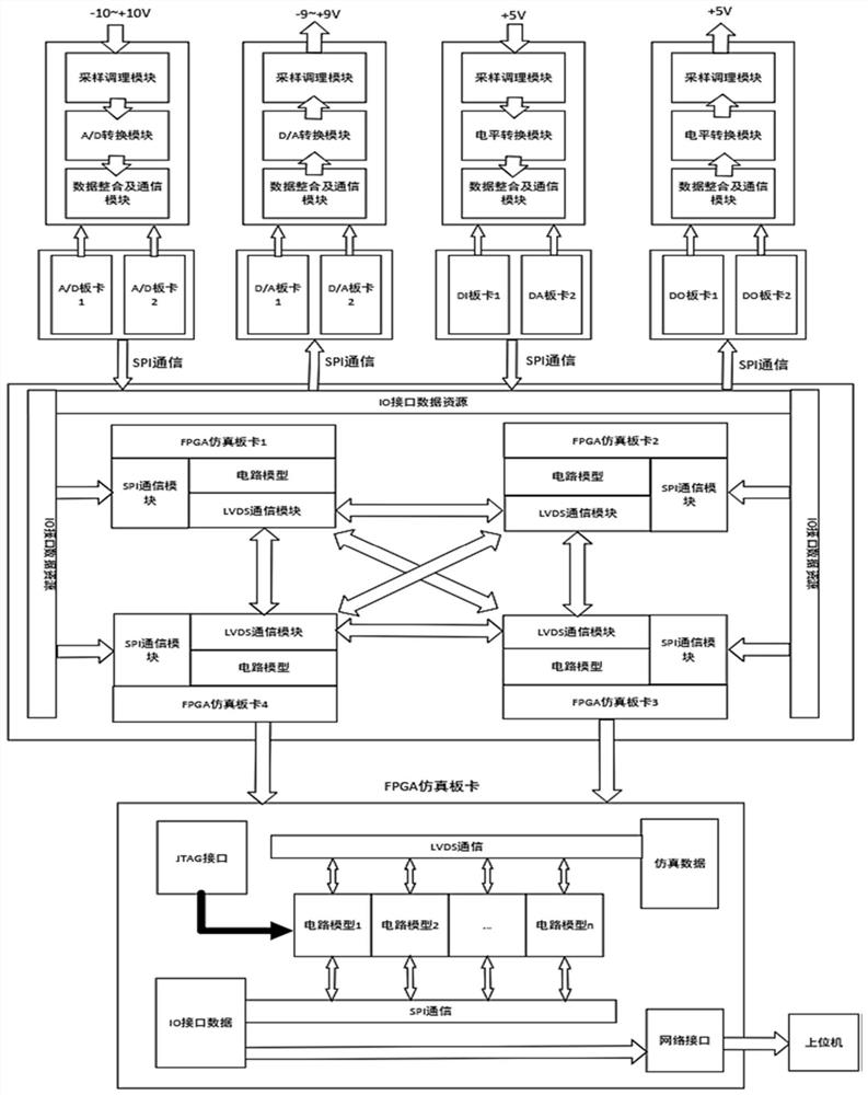
[0029] The present invention relates to an FPGA-based power electronics semi-physical simulation system. In order to increase the number of various interfaces as much as possible and facilitate the expansion of each module and system, the present invention designs all interface modules and simulation calculation modules into an independent board structure , respectively form A / D board, D / A board, DI board, DO board, core computing board (FPGA board), and the data calculation, storage and communication of each board are re...


PUM


Abstract

The invention relates to an FPGA-based power electronic semi-physical simulation system, which comprises an A / D board card, a D / A board card, a DI board card, a DO board card and a core calculation board card which are respectively distributed on five FPGA simulation board cards arranged independently; data calculation, storage and communication of each board card are achieved by adopting an FPGA,and the core computing board card is in communication connection with the A / D board card, the D / A board card, the DI board card and the DO board card. A circuit input part of the system comprises anAD board card and a DI board card, and a circuit output part comprises a DA board card and a DO board card. Compared with the prior art, the system has the advantages that the system simulation capacity is effectively increased, the simulation step length is shortened, the actual operation condition of the system can be reflected more truly, and the like.

Description

technical field [0001] The invention relates to the technical field of power electronics, in particular to an FPGA-based power electronics hardware-in-the-loop simulation system. Background technique [0002] The rapid development of the power electronics industry and the gradual expansion of various power electronic equipment to the high-power field have resulted in higher and higher requirements for the operating environment. Before the actual operation of the device, it is necessary to simulate it. Currently, pure mathematics is used more Simulation, that is, using software to simulate power electronics and power electronics systems, lacks connection with external actual systems and lacks accuracy. [0003] With the development of power electronics technology, traditional pure software simulation is difficult to consider the connection between the simulation model and the external real environment, and even because the actual system is too complex, the accuracy of the bui...

Claims


Application Information

Patent Timeline
Patent Type & Authority Applications(China)
IPC IPC(8): G05B17/02
CPCG05B17/02
Inventor 李厚祥张永明
Owner SHANGHAI DIANJI UNIV
Learn More