
Optical fiber distribution frame

An optical fiber distribution frame and optical fiber technology, which is applied in the field of optical communication, can solve the problems of inability to realize variable speed, no automatic wiring capability, and elevated displacement motion, etc., to achieve improved efficiency, convenient detection and maintenance, and connection. reliable results

Inactive Publication Date: 2020-12-18
吴娟
View PDF0 Cites 0 Cited by
  • Summary
  • Abstract
  • Description
  • Claims
  • Application Information

AI Technical Summary

Problems solved by technology

[0004] The purpose of the present invention is to provide an optical fiber distribution frame to solve the technical problems in the prior art that do not have the ability of automatic wiring and cannot realize the speed-variable increase and flexible displacement movement.

Method used

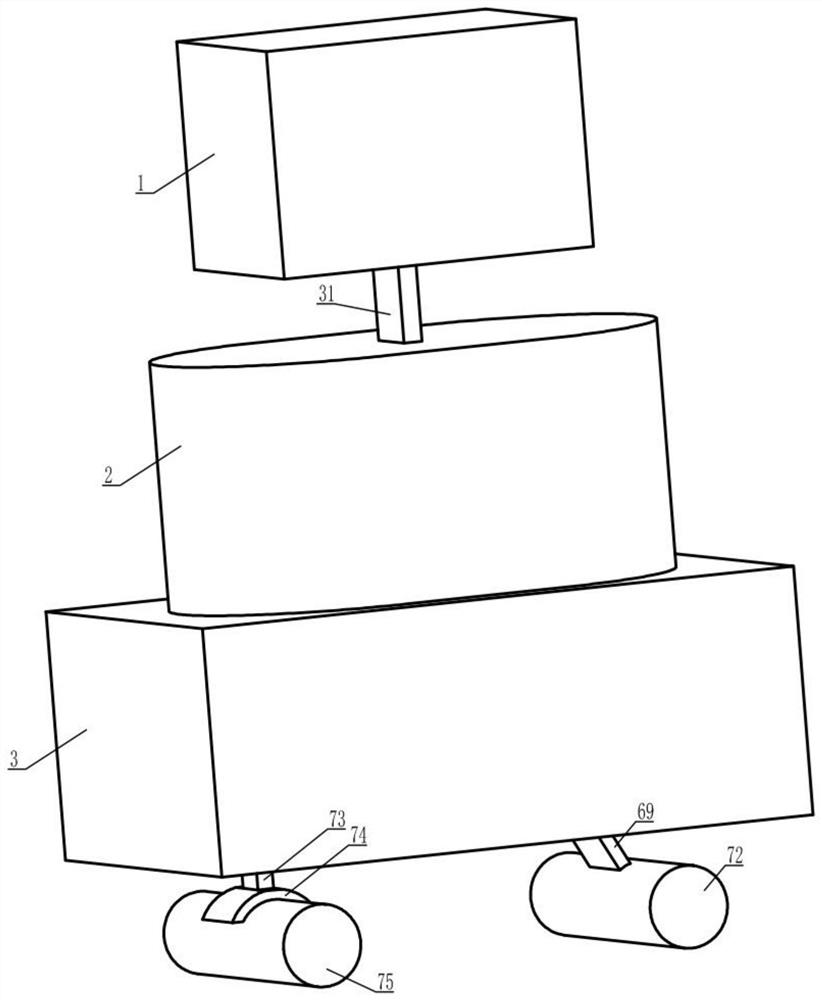
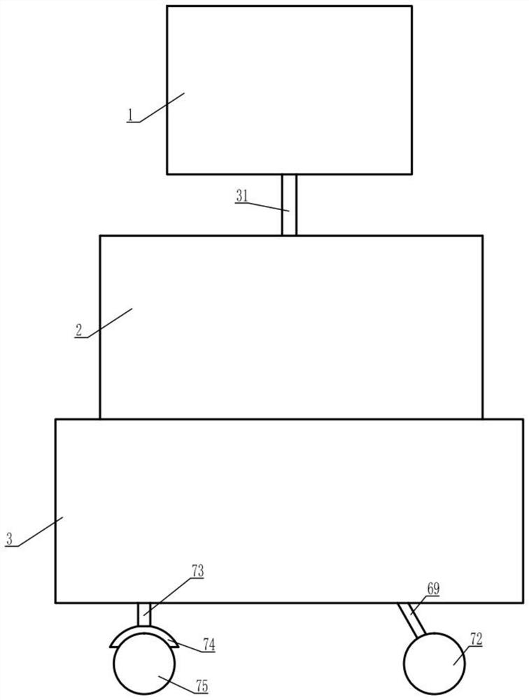
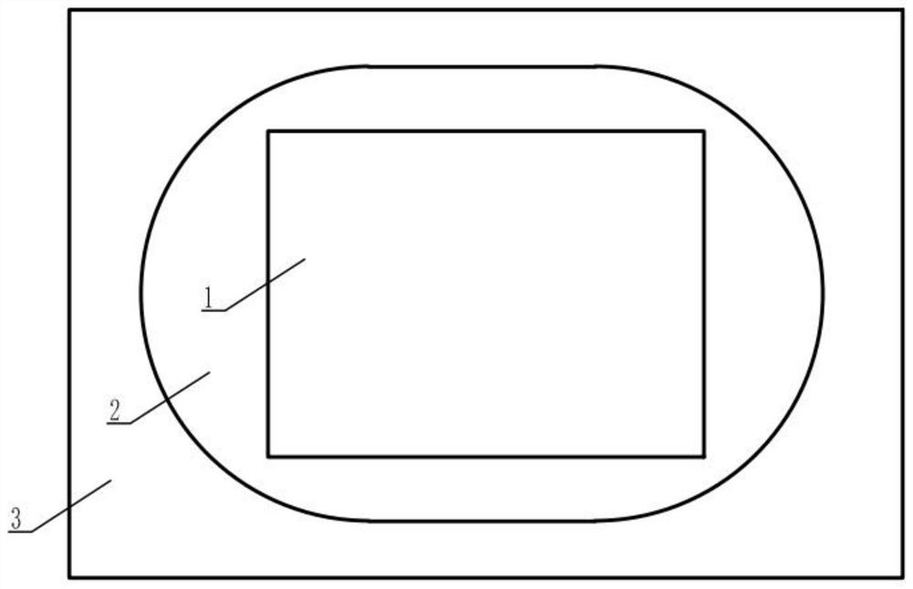

Image

  • Optical fiber distribution frame
  • Optical fiber distribution frame
  • Optical fiber distribution frame

Examples


Embodiment Construction

[0029] The present invention is described in detail below in conjunction with accompanying drawing:

[0030] refer to Figure 1 to Figure 9 , an optical fiber distribution frame provided by the present invention includes a distribution box 1 and a riser 2, the bottom of the distribution box 1 is fixedly connected to the top of the active arm 31, and the bottom of the riser 2 A moving chassis 3 is provided, a wire feeding box 4 is fixed on the inner left side of the wiring box 1, and a motor bottom plate 30 is fixed on the inner left side of the wire feeding box 4, and the motor bottom plate 30 The right side is provided with a motor 29, and the right power output end of the motor 29 is provided with a power shaft 28, and the right end of the power shaft 28 is fixedly connected with the left end of the drive shaft 26 through a coupling 27. The right end of transmission shaft 26 is fixed with second bevel gear 25, and the rear surface of described second bevel gear 25 contacts ...


PUM


Abstract

The invention provides an optical fiber distribution frame which comprises a distribution box and a lifting instrument; the bottom of the distribution box is fixedly connected with the top end of a driving arm, a moving chassis is arranged at the bottom of the lifting instrument, a wire feeding box is fixed to the left side face in the distribution box, a motor bottom plate is fixed to the left side face in the wire feeding box, and a motor is arranged on the right side face of the motor bottom plate. A power shaft is arranged at the right power output end of the motor, the right end of the power shaft is fixedly connected with the left end of a transmission shaft through a coupler, a second bevel gear is fixed to the right end of the transmission shaft, and the rear surface of the secondbevel gear is in contact engagement with the front surface of a first bevel gear;a gear is fixed at the rear end of the first bevel gear; the top end of the gear contacts and meshes with the bottom end of the rack; and the top end of the rack is in contact with the lower surface of the first optical fiber. According to the technical scheme, the technical problems that in the prior art, the automatic wiring capacity is not achieved, and variable-speed rising, flexible displacement movement and the like cannot be achieved are effectively solved, and application and popularization are facilitated.

Description

technical field [0001] The present invention relates to the technical field of optical communication, in particular to an optical fiber distribution frame. Background technique [0002] The optical fiber distribution frame is a wiring connection device between optical fibers, which can conveniently realize the connection, distribution and scheduling of optical fiber lines. With the increasing degree of network integration, the optical-digital hybrid distribution frame integrating ODF, DDF and power distribution unit has appeared, which is suitable for small and medium-sized distribution of fiber to the community, fiber to the building, remote modules and wireless base stations. line system. The optical fiber distribution frame should have the functions of fixing, connecting and protecting optical cables. [0003] Optical fiber distribution frame is one of the essential equipment in optical fiber integrated wiring system. The invention of optical fiber distribution frame ha...

Claims


Application Information

Patent Timeline
IPC IPC(8): G02B6/44
CPCG02B6/4446G02B6/4452
Inventor 吴娟
Owner 吴娟
Learn More