Fan blade deicing device

A technology for fan blades and blades, applied in the field of fan blade deicing devices, can solve the problems of low efficiency, difficult maintenance, high energy consumption, etc., and achieve the effects of low cost, delayed icing, and high thermal efficiency

Pending Publication Date: 2020-12-18
KUNMING UNIV OF SCI & TECH
View PDF0 Cites 5 Cited by
  • Summary
  • Abstract
  • Description
  • Claims
  • Application Information

AI Technical Summary

Problems solved by technology

[0007] The technical problem to be solved by the present invention is: the present invention provides a fan blade deicing device, which is used to overcome the deficiencies of the existing wind farm blade deicing methods such as low efficiency, high energy consumption, and difficult maintenance.

Method used


Image

  • Fan blade deicing device
  • Fan blade deicing device
  • Fan blade deicing device

Examples


Embodiment 1

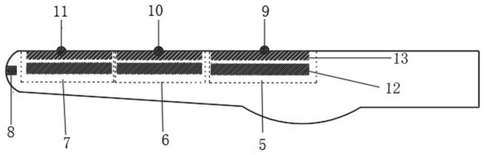
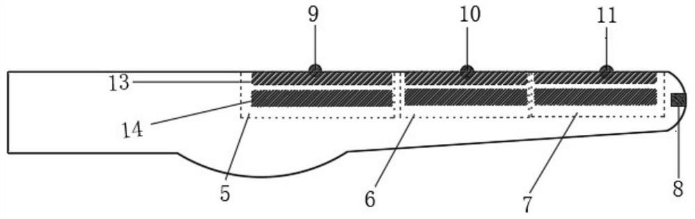
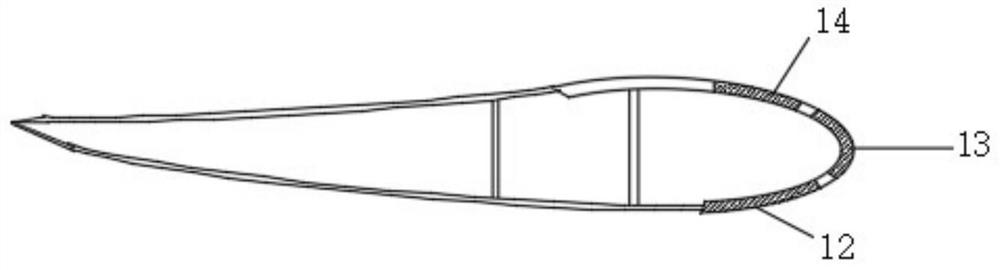
[0036] Embodiment 1: as Figure 1-7As shown, a fan blade deicing device includes a deicing system control cabinet, an external sensor detection device, a ceramic electrothermal film 3 and a nanometer super-hydrophobic coating 1 coated on the outer surface of the fan blade; the deicing system control cabinet adopts PLC controller, the external sensing and detecting device includes an icing sensor and a temperature sensor, and the external sensing and detecting device is connected to the control cabinet of the deicing system; the fan blade is divided into electrothermal film area I5 and electrothermal film area I5 sequentially from the blade root to the blade tip. Area Ⅱ6 and electrothermal film area Ⅲ7, electrothermal film area Ⅰ5, electrothermal film area Ⅱ6 and electrothermal film area Ⅲ7 are respectively equipped with icing sensor Ⅰ9, icing sensor Ⅱ10 and icing sensor Ⅲ11 for real-time monitoring of the temperature of each divided area on the fan blade. The icing situation i...

Embodiment 2

[0052] Embodiment 2, a fan blade deicing device, such as figure 1 , figure 2 As shown, the present invention divides the electric heating of the blade into zones according to the severity of icing in each area of ​​the blade and the power limitation of the conductive slip ring. The fan blade is divided into electrothermal film area I5 (area 1), The electric heating film area Ⅱ6 (area 2) and the electric heating film area Ⅲ7 (area 3), the electric heating film area Ⅰ5, the electric heating film area Ⅱ6 and the electric heating film area Ⅲ7 are equipped with icing sensor Ⅰ9, icing sensor Ⅱ10 and icing sensor Ⅲ11 respectively To monitor the icing situation in each divided area on the fan blades in real time and feed back to the deicing system control cabinet. The icing sensor set uses the blade icing sensor Model 9734-SYSTEM to monitor the icing situation in real time and feed back to the deicing system The control cabinet is equipped with a temperature sensor 8 outside the bla...


PUM


Abstract

The invention relates to a fan blade deicing device. The fan blade deicing system comprises a deicing system control cabinet, an external sensing detection device, ceramic electric heating films and anano super-hydrophobic coating, wherein the nano super-hydrophobic coating coats the outer surface of a fan blade, the external sensing detection device is connected with the deicing system control cabinet; the fan blade is sequentially divided into a plurality of monitoring areas from a blade root to a blade tip, icing sensors are arranged outside the monitoring areas divided on the fan blade correspondingly, each monitoring area is divided into independent heating piece areas of a blade front wing face, a front edge hot knife and a blade rear wing face, and a ceramic electric heating film is arranged in each heating piece area; the deicing system control cabinet is connected with the ceramic electric heating films; and a temperature sensor is arranged outside the fan blade tip. According to the fan blade deicing system, the efficient deicing of key areas can be achieved; and not only is unnecessary energy consumption of non-icing areas greatly reduced, but also the deicing efficiency is improved, and the whole system is more efficient and energy-saving.

Description

technical field [0001] The invention relates to a fan blade deicing device, which belongs to the technical field of wind power generation. Background technique [0002] With the continuous development of the world today, the demand for energy is also increasing. As a renewable energy with great potential, wind energy has been highly valued by governments of various countries, and the investment is also increasing. [0003] Wind power generation is to use the wind to drive the blades of the fan to rotate, and then drive the high-speed shaft to rotate through the speed-increasing gearbox, thereby promoting the wind turbine to generate electricity. Wind power generation is a clean and efficient way of generating electricity. However, wind power generators are generally erected in cold regions or high-altitude regions, and face the test of the cold external environment during winter operation. Among them, the icing of wind turbine blades is one of the important challenges. [...

Claims


Application Information

Patent Timeline
Patent Type & Authority Applications(China)
IPC IPC(8): F03D80/40F03D80/60
CPCF03D80/40F03D80/60Y02E10/72
Inventor 罗小林张林通张敬华
Owner KUNMING UNIV OF SCI & TECH
Why Eureka
Try Eureka