


Quick Research
Generate reliable direction feasibility study reports for your R&D in just a few steps.

Technical Q&A
Discover and master advanced knowledge NOW. Basics, ideas, possibilities, all at once.

Find Solutions
As an expert in R&D theories, this can generate solutions to your technical problems instantly.

Evaluate Feasibility
Analyze your overall solution with one click, know your potential R&D risks in advance.

Monitor Landscape
Get weekly tech updates, stay abreast of the latest tech innovations and key insights.
Reinforced movable buckle
A technology of movable buckles and reinforcement holes, which is applied in the direction of formwork/formwork members, formwork/formwork/work frame, and connection parts of formwork/formwork/work frame, etc. Narrow, construction and other problems, to achieve the effect of improving the explosion point phenomenon of the wall and strengthening the explosion point phenomenon of the wall
- Summary
- Abstract
- Description
- Claims
- Application Information
AI Technical Summary
Problems solved by technology
Method used
Image


Examples
Embodiment 1
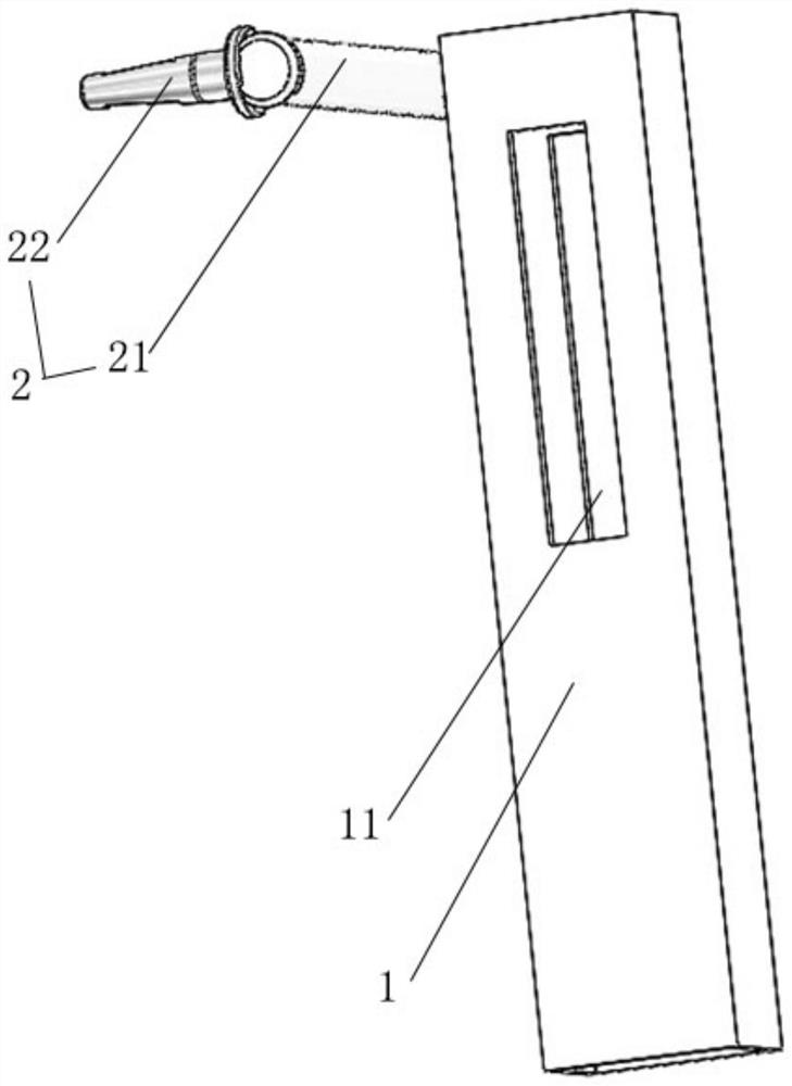
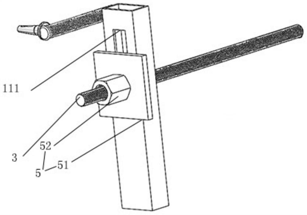
[0022] Such as Figure 1-2 As shown, a reinforced movable buckle includes a reinforcing piece 1 connected to the horizontal back of the wall and a side positioning piece 2 arranged on the outside of the reinforcing piece 1, and a misplaced reinforcing hole 11 is opened on the reinforcing piece 1, so that The dislocation reinforcement hole 11 includes an upper connection surface 111 connected to the reinforcement rod 3 , and the upper connection surface 111 is not at the same level as the highest point of the side positioning member 2 . The side positioning member 2 includes a connecting rod 21 connected with the reinforcing member 1 and an insertion positioning head 22 arranged on one end side of the connecting rod 21, and the insertion positioning head 22 is connected with the vertical back of the side.
[0023] The present invention is used for lateral fixation by designing the side positioning part 2, and designing a dislocation reinforcement hole 11 that is not at the same...
Embodiment 2
[0029] Based on embodiment 1, the difference from embodiment 1 is:
[0030] In the long-term use process, external force may form a collision on the wall or the change of geological structure may have an impact on the wall, thereby causing the wall to change. Make the angle between them change or the depth change. Such as Figure 5 As shown, the dislocation reinforcement hole 11 is provided with a reinforcement device 4 arranged on the outside of the reinforcement rod 3, and the reinforcement device 4 includes a connecting elastic member 41 connected to the inner wall of the dislocation reinforcement hole 11 and can be connected to the The clamping side plate 42 connected to the reinforcing rod 3 , the other side of the clamping side plate 42 connected to the reinforcing rod 3 is connected to the connection elastic member 41 . In the long-term process, if there is a change, the design of the reinforcement device 4 is to protect the reinforcing movable buckle itself after the...
PUM
 Abstract
Description
Claims
Application Information
 - R&D Engineer
- R&D Manager
- IP Professional
- Industry Leading Data Capabilities
- Powerful AI technology
- Patent DNA Extraction
Browse by: Latest US Patents, China's latest patents, Technical Efficacy Thesaurus, Application Domain, Technology Topic, Popular Technical Reports.
© 2024 PatSnap. All rights reserved.Legal|Privacy policy|Modern Slavery Act Transparency Statement|Sitemap|About US| Contact US: help@patsnap.com