
Charging pile thermal management system

A thermal management system and charging pile technology, applied in charging stations, electric vehicle charging technology, electric vehicles, etc., can solve the problems of occupying the installation space of charging piles, high cost, etc., so as to improve the cooling rate, improve the efficiency, and reduce the use cost. Effect

Pending Publication Date: 2020-12-18
ZEPHYR INTELLIGENT SYST SHANGHAI CO LTD
View PDF0 Cites 1 Cited by
  • Summary
  • Abstract
  • Description
  • Claims
  • Application Information

AI Technical Summary

Problems solved by technology

If a heat exchange system is directly added to the charging pile, it will occupy a large amount of charging pile installation space, and secondly, the cost of installing a heat exchange system for each charging pile will be high

Method used


Image

  • Charging pile thermal management system

Examples


Embodiment Construction

[0027] Embodiments of the present invention will be described in further detail below in conjunction with the accompanying drawings.

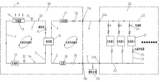
[0028] The charging pile thermal management system of this embodiment includes: a thermal management unit 30 , a charging pile module 20 , a sixth conduit 6 , and a seventh conduit 7 . The heat management unit 30 includes a device housing 11, a compressor 12, a first conduit 1, a condenser 13, a blower 14, a second conduit 2, an expansion valve 15, a plate heat exchanger 16, a third conduit 3, a heating Device 17, water pump 18, fourth conduit 4, fifth conduit 5; wherein compressor 12, condenser 13, blower 14, expansion valve 15, plate heat exchanger 16, heater 17, water pump 18 and each conduit are all installed in device housing 11. The compressor 12, the condenser 13, the expansion valve 15, and the plate heat exchanger 16 form a closed loop through the first conduit 1, the second conduit 2, and the third conduit 3, and a refrigerant flows ...


PUM


Abstract

The invention discloses a charging pile thermal management system. The system comprises a thermal management unit, a charging pile module, an expansion water tank and a connecting guide pipe; the thermal management unit comprises a device shell, a compressor, a condenser, an air blower, an expansion valve, a plate heat exchanger, a water pump, a heater and the like; and the charging pile module comprises a plurality of charging piles, a circulating main pipe, circulating branch pipes, waterway electromagnetic valves and branch pipe water temperature sensors. According to the system, by controlling the temperature of a coolant to exchange heat in the charging piles, the cooling rate of the charging piles is greatly increased, and thus the charging piles are greatly improved in the aspects of temperature control stability, temperature difference degree, efficiency and the like. The system is provided with the thermal management unit and the charging pile module which are separated, the thermal management unit and the charging pile module are in butt joint through four butt joint ports, the thermal management unit can be installed at positions farther than the charging pile module, and thus selectable installation positions of the thermal management unit are greatly increased without occupying the charging pile installation space.

Description

technical field [0001] The invention belongs to the field of public charging of new energy vehicles, in particular to a charging pile thermal management system. Background technique [0002] With the development of the new energy vehicle market, there are more and more charging piles. The heat released by the charging piles during operation will affect the service life and cause burns and fires. [0003] At present, in the field of public charging of new energy vehicles, there is no technology to manage the heat source of charging piles. Traditional charging piles release heat through air cooling and air heat exchange, and the efficiency is slow. If a heat exchange system is directly added to the charging pile, it will occupy a large amount of charging pile installation space, and secondly, the cost of installing a heat exchange system for each charging pile will be high. Contents of the invention [0004] The purpose of the present invention is to solve the problems ...

Claims


Application Information

Patent Timeline
Patent Type & Authority Applications(China)
IPC IPC(8): B60L53/302B60L53/31
CPCB60L53/302B60L53/31Y02T10/70Y02T10/7072Y02T90/12
Inventor 芮晓飞刘海涛
Owner ZEPHYR INTELLIGENT SYST SHANGHAI CO LTD
Learn More