Bridge anti-collision device

An anti-collision device and bridge technology, applied in the direction of bridges, bridge parts, bridge construction, etc., can solve the problems of high maintenance cost, unsatisfactory energy absorption effect of steel materials, and easy corrosion of steel structures.

Pending Publication Date: 2020-12-15
江苏新合力传热设备有限公司
View PDF0 Cites 0 Cited by
  • Summary
  • Abstract
  • Description
  • Claims
  • Application Information

AI Technical Summary

Problems solved by technology

[0003] However, the steel structure is easy to rust in water, the maintenanc...

Method used


Image

  • Bridge anti-collision device
  • Bridge anti-collision device
  • Bridge anti-collision device

Examples


Embodiment Construction

[0034] The specific implementation of the bridge anti-collision device of the present invention will be described in detail below in conjunction with the accompanying drawings.

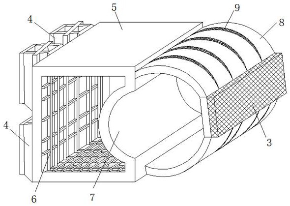
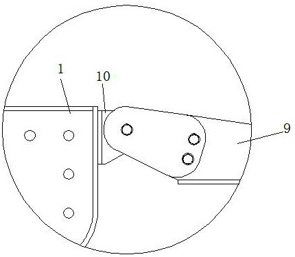
[0035] See attached figure 1 , 2 ,The bridge anti-collision device includes an anti-collision combination composed of a rigid body 1 and an impact body 2. The impact body 2 is arranged outside the rigid body 1. The impact body 2 is a hollow barrel-shaped structure. Airbags are set inside. A plurality of fenders 4 are arranged inside the rigid body 1 .

[0036] The rigid body 1 includes a shell 5 and a skeleton structure 6 provided in the shell 5. The skeleton structure 6 is located on the walls around the interior of the shell 5, and a cavity is formed in the middle. The skeleton structure 6 is formed by interlacing and fixing transverse bones and longitudinal bones, so that The rigid body 1 reaches the design strength. The outer side of the rigid body 1 is provided with an arc-shaped groove 7 . ...


PUM


Abstract

The invention relates to the technical field of bridges, and discloses a bridge anti-collision device. The bridge anti-collision device comprises an anti-collision assembly composed of a rigid body and an impact body, wherein the impact body is arranged on the outer side of the rigid body and is of a hollow barrel-shaped structure; an impact block is arranged on the forefront portion of the impactbody; and an air bag is arranged in the impact body. The bridge anti-collision device effectively absorbs impact force of ships on piers and protects a bridge.

Description

technical field [0001] The invention relates to the technical field of bridges, in particular to a bridge anti-collision device. Background technique [0002] A bridge refers to a building built for roads to cross natural or artificial obstacles. It is erected on rivers, lakes and seas to allow vehicles and pedestrians to pass smoothly. A bridge is generally composed of a superstructure, a substructure and ancillary structures. The superstructure mainly refers to the bridge span structure and support system. The substructure includes abutments, piers and foundations. , diversion engineering, etc. When the ship passes the bridge, due to the action of the water flow, it may hit the pier and cause damage to the pier. In order to prevent such accidents, newly-built bridges will choose protective measures in dangerous areas to minimize the collision damage of ships to bridges. Most of the existing protective devices are protective covers of steel structures, which protect brid...

Claims


Application Information

Patent Timeline
IPC IPC(8): E02B3/26E01D19/02
CPCE01D19/02E02B3/26Y02A30/30
Inventor 是旺道
Owner 江苏新合力传热设备有限公司
Why Eureka
Try Eureka