one for co 2 Reduced photocatalyst and preparation method thereof

A photocatalyst and catalyst technology, applied in the direction of physical/chemical process catalysts, chemical instruments and methods, separation methods, etc., can solve problems such as large impact on profit and income, damage to geological structures, secondary leakage, etc., to achieve improved photocatalytic activity , increase the lifespan, and improve the transmission rate

Active Publication Date: 2022-02-08
HUNAN UNIV
View PDF3 Cites 0 Cited by
  • Summary
  • Abstract
  • Description
  • Claims
  • Application Information

AI Technical Summary

Problems solved by technology

However, CO 2 Capture technology solutions generally have disadvantages such as high cost, and the profit income is greatly affected by local policies, and the post-capture CO 2 The degree of utilization also becomes a necessary consideration for the entire capture project
Currently, large-scale CO 2 Storage in the ground is still the main treatment method, but there is CO 2 Hazards such as secondary leakage and damage to geological structures

Method used


Image

  • one for co  <sub>2</sub> Reduced photocatalyst and preparation method thereof
  • one for co  <sub>2</sub> Reduced photocatalyst and preparation method thereof
  • one for co  <sub>2</sub> Reduced photocatalyst and preparation method thereof

Examples


Embodiment 1

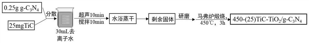
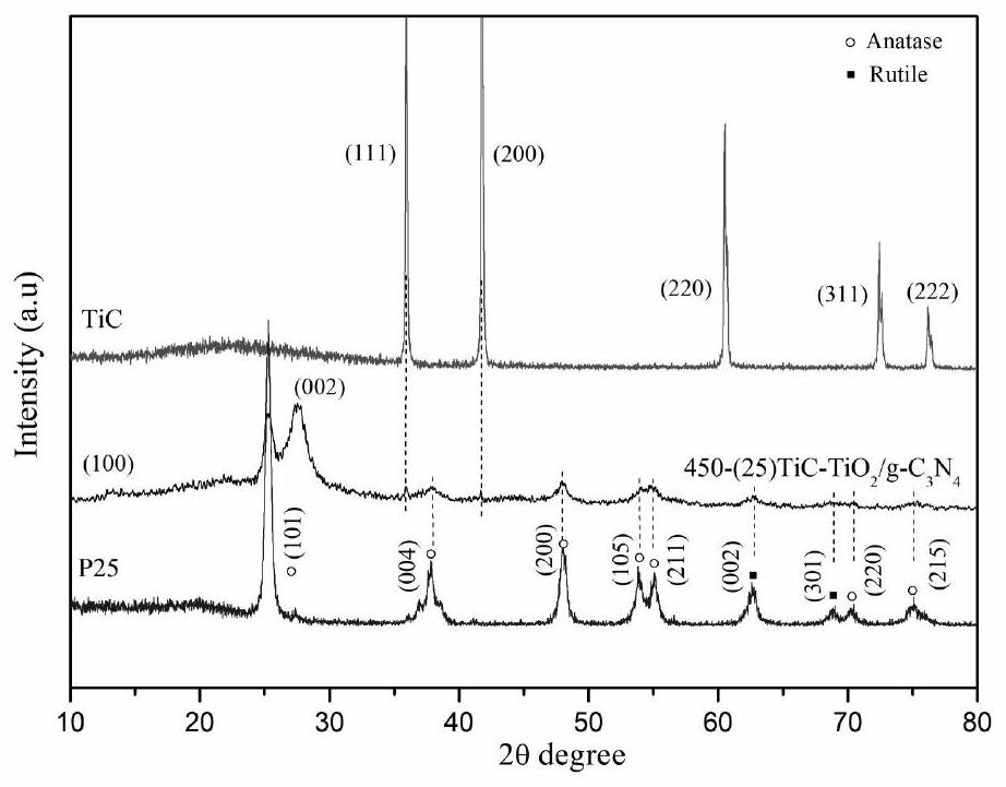
[0038]Embodiment 1: composite catalyst TiC-TiO 2 / g -C 3 N 4 method of preparation. 0.25g g-C 3 N 4 Disperse in a beaker filled with 30mL of deionized water, weigh 25mg of TiC and put it into the above mixture, and perform ultrasonic treatment for 10min and stirring for 10min, wherein the stirring speed is 1000 rad / min, and then transfer the mixture to a water bath , and evaporated to dryness in a water bath at 80° C. at a speed of 500 rad / min. After evaporating to dryness, the remaining solid was taken out and ground, and then placed in a muffle furnace for calcination. The calcination temperature was 450°C, the heating rate was 5°C / min, and the calcination time was 3h, so that TiC was partially oxidized to TiO 2 , the obtained sample is recorded as 450-(25)TiC-TiO 2 / g -C 3 N 4 . attached figure 1 Represents 450-(25)TiC-TiO 2 / g -C 3 N 4 A schematic diagram of the preparation process.

Embodiment 2

[0041] Embodiment 2: preparation method is the same as embodiment 1, and its difference is that in the preparation process of catalyst, directly to g-C 3 N 4 Add 10mg TiC and 15mg TiO to the mixture 2 Nanoparticles (5–7nm) in tube furnaceN 2 Calcined at 550°C for 3 hours in the atmosphere, the heating rate was 5°C / min, TiC was not oxidized, and the obtained sample was recorded as 450-TiC / TiO 2 / g -C 3 N 4 .

Embodiment 3

[0042] Example 3: The preparation method is the same as in Example 1, the difference is that during the preparation of the catalyst, the calcination temperature in the muffle furnace is 400 ° C, and the obtained sample is recorded as 400-(25)TiC-TiO 2 / g -C 3 N 4 .


PUM


Abstract

The present invention is a method for CO 2 Reduced photocatalyst and preparation method thereof, photocatalyst of the present invention is made of g-C 3 N 4 It is prepared by high-temperature calcination and partial oxidation after compounding with transition metal carbides. It has "Z" type carrier transport characteristics, and the formed "Z" type heterojunction reduces the hole-electron recombination rate, and the oxidation reaction and reduction on the catalyst Reactions are separated, thereby enhancing the photocatalytic CO 2 Reduction efficiency and stability. The photothermal effect caused by the large specific surface area of ​​the catalyst and its strong light absorption intensity improves the photocatalytic activity, and the products such as CO are easily desorbed on the surface, which is conducive to the reuse of active sites and enhances the stability of the photocatalyst. . The catalyst of the present invention is in the photocatalytic CO 2 The reduction field has good application prospects, its raw materials are relatively cheap, its preparation method and operation are simple, and it is suitable for large-scale production.

Description

technical field [0001] The invention belongs to photocatalytic CO 2 Utilization field, specifically related to a CO 2 Reduced photocatalyst and method for its preparation. [0002] technical background [0003] CO 2 Capture and utilization has always been a hot topic in human research. CO 2 It is the culprit that causes the global warming effect, and as a C source, it can become a raw material for many energy reactions. Therefore, for CO 2 It is captured and then utilized as a resource to prepare a high-energy fuel substance, which has a very high research value. [0004] Currently CO 2 There are three main technical solutions for the capture of CO2, namely pre-combustion capture, oxygen-enriched combustion, and post-combustion capture. These three methods are currently becoming mature. Globally, CO 2 Capture items and capture capabilities grow rapidly. However, CO 2 Capture technology solutions generally have disadvantages such as high cost, and the profit income is...

Claims


Application Information

Patent Timeline
Patent Type & Authority Patents(China)
IPC IPC(8): B01J27/24B01J27/22B01J35/10B01D53/86B01D53/62C01B32/40
CPCB01J27/24B01J27/22B01J35/1004B01J35/004B01D53/8671C01B32/40B01D2257/504Y02C20/20
Inventor 罗潇李子怡陈明梁志武
Owner HUNAN UNIV
Why Eureka
Try Eureka