
Level shifter

A level shifter and device technology, applied in the direction of electrical components, logic circuits, logic circuit connection/interface layout, etc., can solve the problems of high cost, large static power consumption, etc., achieve low cost, strong driving ability, and prevent punch-through The effect of current

Pending Publication Date: 2020-12-11
WILL SEMICON (SHANGHAI) CO LTD
View PDF0 Cites 4 Cited by
  • Summary
  • Abstract
  • Description
  • Claims
  • Application Information

AI Technical Summary

Problems solved by technology

[0003] The technical problem to be solved by the present invention is to overcome the defects of high cost and large static power consumption in the prior art in which the low-voltage logic signal is converted to the high-voltage driving signal that changes to the ground level, and provides a high-speed, Low-power, high-voltage-resistant and low-cost level shifter for high-voltage drive signal conversion from low-voltage logic signals to ground levels

Method used


Image

  • Level shifter
  • Level shifter

Examples


Embodiment Construction

[0054] The present invention is further illustrated below by means of examples, but the present invention is not limited to the scope of the examples.

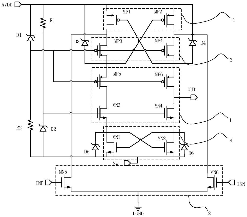
[0055] Such as figure 2 As shown, this embodiment provides a level shifter, including an output terminal OUT, a first input terminal INP, a second input terminal INN, a latch circuit 4, a level flip pull-down circuit 2, and a voltage clamping circuit 1 , Anti-current backflow circuit 3, a first pull-up device, a second pull-up device, a first pull-down device and a second pull-down device.

[0056] In this embodiment, the first pull-up device, the second pull-up device, the first pull-down device and the second pull-down device are all realized by Zener diodes, corresponding to figure 2 The third Zener diode D3, the fourth Zener diode D4, the fifth Zener diode D5 and the sixth Zener diode D6. It should be noted that, in other implementation manners based on the concept of the present invention, the first pull-up device, th...


PUM


Abstract

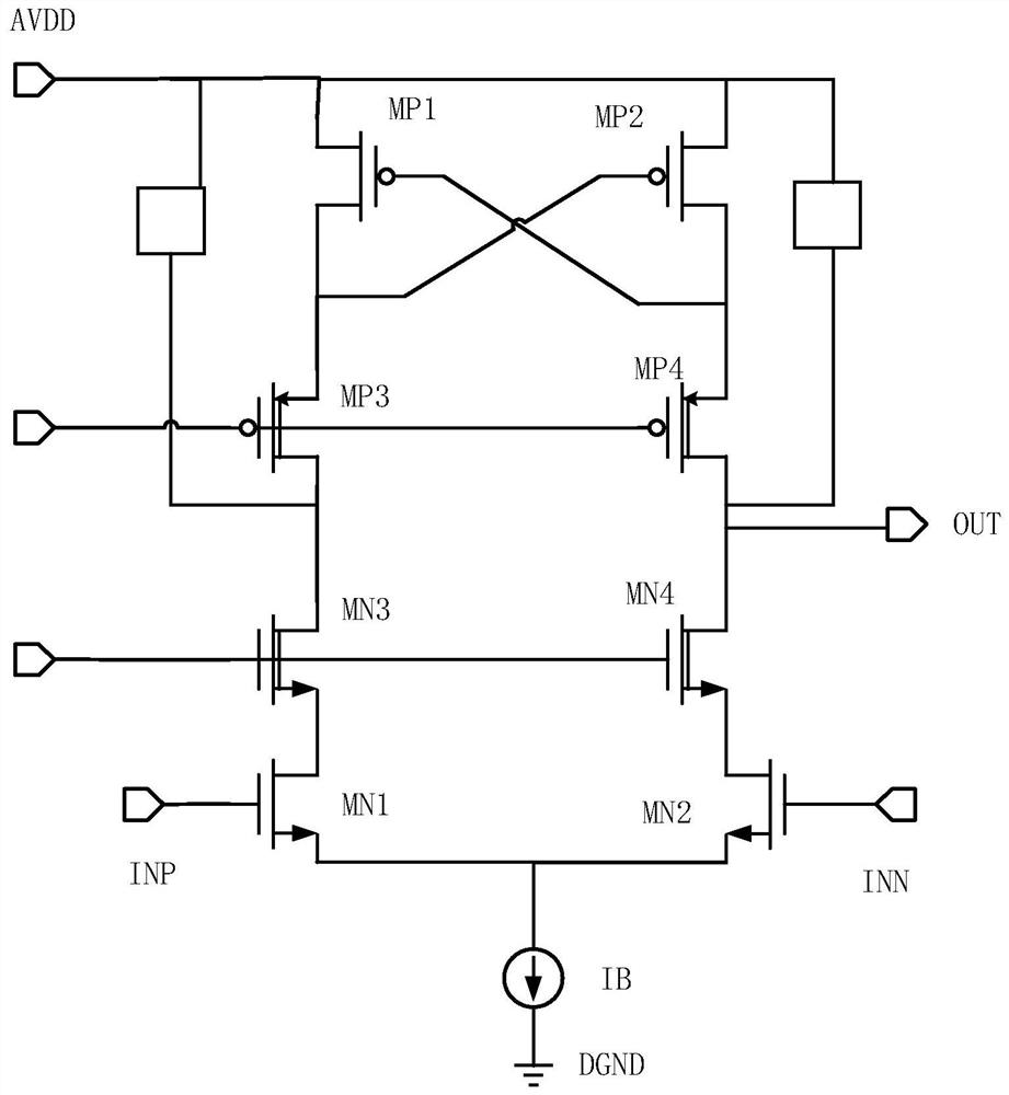
The invention discloses a level shifter which comprises an output end, a first input end, a second input end, a latch circuit, a level overturning pull-down circuit and a voltage clamping circuit. Thelatch circuit comprises a first PMOS tube, a second PMOS tube, a first NMOS tube and a second NMOS tube. The voltage clamping circuit comprises a first clamping device, a second clamping device, a third NMOS tube, a fourth NMOS tube, a fifth PMOS tube and a sixth PMOS tube. The level overturning pull-down circuit comprises a fifth NMOS transistor and a sixth NMOS transistor; the first clamping device is used for clamping the voltage of the grid electrodes of the fifth PMOS tube and the sixth PMOS tube; the second clamping device is used for clamping the voltage of the grid electrodes of the third NMOS tube and the fourth NMOS tube. Under the condition that the ground level of the high-voltage driving signal is changed, level conversion is completed at high speed and low power consumption,and the cost is low. A gate oxide layer of a transistor device in the level shifter can be protected from being broken down through the voltage clamping circuit, and the high voltage of the output end is isolated; zero static power consumption and rapid level overturning are achieved through the latch circuit and the level overturning pull-down circuit, and high driving capacity is achieved.

Description

technical field [0001] The invention relates to the technical field of level shifters, in particular to a level shifter applied to conversion of high-voltage drive signals from low-voltage logic signals to ground levels. Background technique [0002] In circuit applications, there is a need for level conversion of low-voltage logic signals to high-voltage drive signals that change from ground level. For example, in a dual NMOS (N-type metal-oxide-semiconductor) drive circuit in a traditional synchronous switching power supply topology, the NMOS gate drive for the high-voltage side involves a high-voltage drive signal that changes from a low-voltage logic signal to a ground level the process of level shifting. When using a bootstrap circuit to drive the NMOS gate on the high voltage side, if the bootstrap voltage is higher than 5V (volts), it may break down the thin gate oxide device in the traditional process. In order to solve the hazards of high bootstrap voltage, the tr...

Claims


Application Information

Patent Timeline
IPC IPC(8): H03K19/0185
CPCH03K19/018507
Inventor 黄武李彬周伟雄
Owner WILL SEMICON (SHANGHAI) CO LTD
Learn More