A Buck-Boost Controller Based on Current Mode

A current mode and controller technology, applied in control/regulation systems, instruments, electrical components, etc., can solve the problems of high dynamic loss of switching and difficult seamless switching, and achieve the effect of reducing dynamic loss and smooth and seamless switching.

Active Publication Date: 2021-02-09
SHENZHEN INJOINIC TECH
View PDF8 Cites 0 Cited by
  • Summary
  • Abstract
  • Description
  • Claims
  • Application Information

AI Technical Summary

Problems solved by technology

However, at present, it is difficult for buck-boost converters of various architectures to achieve seamless switching between boost and buck, and even switch all four switching tubes in one cycle, resulting in more switching dynamic losses.

Method used


Image

  • A Buck-Boost Controller Based on Current Mode
  • A Buck-Boost Controller Based on Current Mode
  • A Buck-Boost Controller Based on Current Mode

Examples


Embodiment

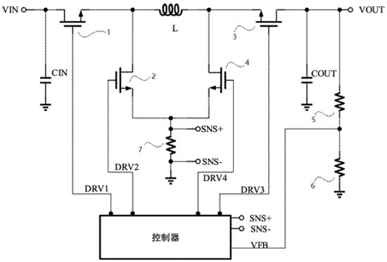
[0037] refer to figure 1 , figure 1 It shows a buck-boost converter composed of a controller, a voltage feedback circuit and a current sampling circuit. The buck-boost converter mainly includes two parts, namely the core controller and the voltage and current feedback loop that cooperates with the core controller , the controller outputs a DRV1 signal, a DRV2 signal, a DRV3 signal, and a DRV4 signal, and the voltage feedback loop includes a first switching tube 1, a second switching tube 2, a third switching tube 3 and a fourth switching tube 4, so The drain of the first switching tube 1 is connected to the VIN input signal, the gate of the first switching tube 1 is connected to the DRV1 signal of the controller, and the source of the first switching tube 1 is connected to the drain of the second switching tube 2; The drain of the third switching tube 3 is connected to the VOUT output signal, the grid of the third switching tube 3 is connected to the DRV3 signal of the contro...


PUM


Abstract

A buck-boost controller based on current mode, comprising: a controller, a voltage feedback loop, and a current sampling circuit, the drain of the first switching tube is connected to the VIN input signal, and the gate of the first switching tube is connected to The DRV1 signal of the controller, the source of the first switch tube is connected to the drain of the second switch tube; the drain of the third switch tube is connected to the VOUT output signal, and the gate of the third switch tube is connected to the DRV3 of the controller signal, the source of the third switching tube is connected to the drain of the fourth switching tube; the source of the second switching tube and the source of the fourth switching tube are connected to the current sampling resistor, and the gate of the second switching tube connected to the DRV2 signal of the controller; the gate of the fourth switching tube is connected to the DRV4 signal of the controller, and the present invention realizes smooth and seamless switching of various modes from boost to boost to boost.

Description

technical field [0001] The invention relates to the field of buck-boost converters, in particular to a buck-boost controller based on a current mode. Background technique [0002] The typical configuration of a four-switch buck-boost converter is as follows: the controller provides periodic PWM control signals, and the driver drives four switches, inductors and output capacitors respectively. [0003] Now there are various architectures to realize the functions of the controller, such as peak current mode, average current mode. However, it is difficult for current buck-boost converters of various architectures to achieve seamless switching between boost and buck, and even switches all four switching tubes in one cycle, resulting in more switching dynamic losses. [0004] It is not difficult to see that there are many problems in the prior art. Contents of the invention [0005] Therefore, in order to solve the above-mentioned problems in the prior art, the present invent...

Claims


Application Information

Patent Timeline
Patent Type & Authority Patents(China)
IPC IPC(8): H02M3/156H02M3/158
CPCH02M3/156H02M3/1582H02M1/0009H02M1/0054H02M3/1566Y02B70/10
Inventor 黄洪伟
Owner SHENZHEN INJOINIC TECH
Why Eureka
Try Eureka