Capacitive current transformer

A technology of capacitive current and transformer, applied in the direction of inductor, transformer/inductor circuit, transformer/inductor coil/winding/connection, etc., to achieve active filter power factor, huge energy saving effect, and improve power factor effect

Inactive Publication Date: 2020-12-11
尤大千
View PDF1 Cites 1 Cited by
  • Summary
  • Abstract
  • Description
  • Claims
  • Application Information

AI Technical Summary

Problems solved by technology

No one has ever used a capacitor as an active current source, so that it has multiple functions of reducing the input active current of the power supply, suppressing high-order harmonics, and improving power factor.

Method used


Image

  • Capacitive current transformer
  • Capacitive current transformer
  • Capacitive current transformer

Examples


Embodiment Construction

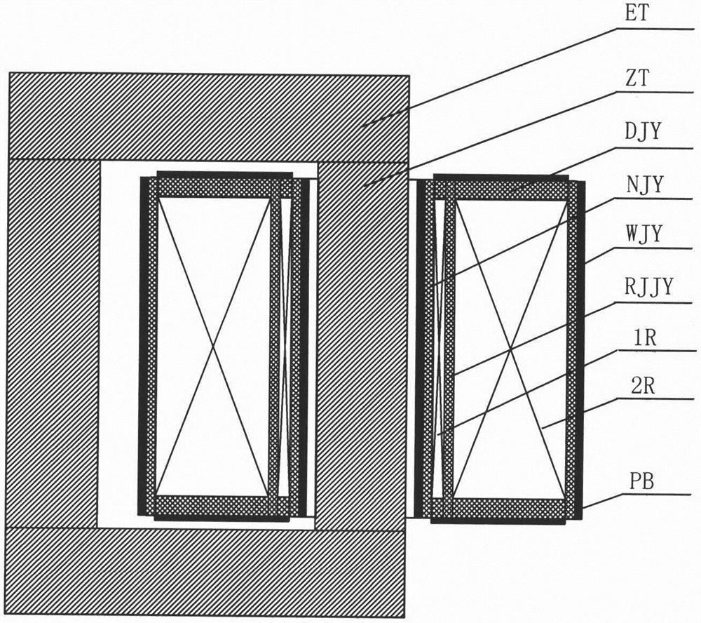
[0084] Embodiments of the present invention are described in further detail below in conjunction with the accompanying drawings

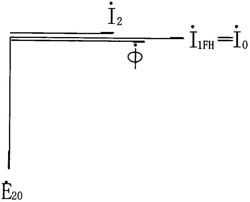
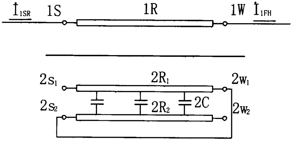
[0085] The invention breaks the traditional concept of strictly preventing the occurrence of dangerous no-load potential when the current transformer is open-circuited twice, and designs the secondary winding of the current transformer as a capacitive winding. Using phase-shifting technology, the high no-load potential generated when the secondary winding is open is deliberately added to the two poles of the capacitor, so that the secondary capacitor current generated by it is fed back to the primary side, basically the same phase or close to the same phase as the primary side load current, Therefore, it can play a role of positive feedback compensation for the primary load current. Then the capacitive current can become the active current delivered to the load side, partially replacing the input current of the power supply. And the capacitor can b...


PUM


Abstract

A capacitive current transformer structurally comprises a primary winding, a secondary winding and an annular iron core. The secondary winding is composed of one or more groups of capacitive windings,different wiring modes are adopted, high potential generated when the secondary winding is in an open circuit state is added to the two poles of the capacitor, the positive feedback capacitor currentinducted by the secondary winding is close to the same primary load current in the same phase, and therefore the power input current is reduced, and the energy-saving effect is achieved. Meanwhile, higher harmonic current can be suppressed, the power factor of a power grid is improved, and the starting current of the motor and the no-load closing magnetizing inrush current of the transformer arereduced.

Description

technical field [0001] The invention relates to a current transformer for high-voltage or low-voltage power supply and distribution lines. In particular, it relates to a capacitive current transformer in which the secondary winding is a capacitive winding operated in an open circuit. Background technique [0002] Current transformers used in high and low voltage power grids are used for measurement or protection devices. The primary and secondary windings are inductive elements wound on the magnetic circuit of the closed iron core. The primary winding usually has only one or two turns, which are directly connected in series in the main circuit, and a large current passes through the circuit. The secondary winding is designed as many turns, through a low-impedance circuit, a small current is induced, and it is connected to a measuring instrument or a protection device. The designed ampere-turns of the primary and secondary windings of this current transformer are the same, ...

Claims


Application Information

Patent Timeline
IPC IPC(8): H01F38/30H01F27/28H01F27/32H01F27/34H01F27/42
CPCH01F27/2847H01F27/2852H01F27/324H01F27/34H01F27/427H01F38/30H01F2038/305
Inventor 不公告发明人
Owner 尤大千
Why Eureka
Try Eureka