
Underwater ultrasonic cavitation field characteristic automatic measurement and visualization system and method

A technology for automatic measurement, cavitation field, applied in the direction of vibration measurement, measurement vibration, measurement device, etc. in fluid

Inactive Publication Date: 2020-12-11
CHINA UNIV OF PETROLEUM (EAST CHINA)
View PDF9 Cites 4 Cited by
  • Summary
  • Abstract
  • Description
  • Claims
  • Application Information

AI Technical Summary

Problems solved by technology

However, there are few methods that can characterize the sound field with both qualitative and quantitative measurements, and there are few methods that replace manual measurements with automated equipment

Method used


Image

  • Underwater ultrasonic cavitation field characteristic automatic measurement and visualization system and method
  • Underwater ultrasonic cavitation field characteristic automatic measurement and visualization system and method
  • Underwater ultrasonic cavitation field characteristic automatic measurement and visualization system and method

Examples


Embodiment 1

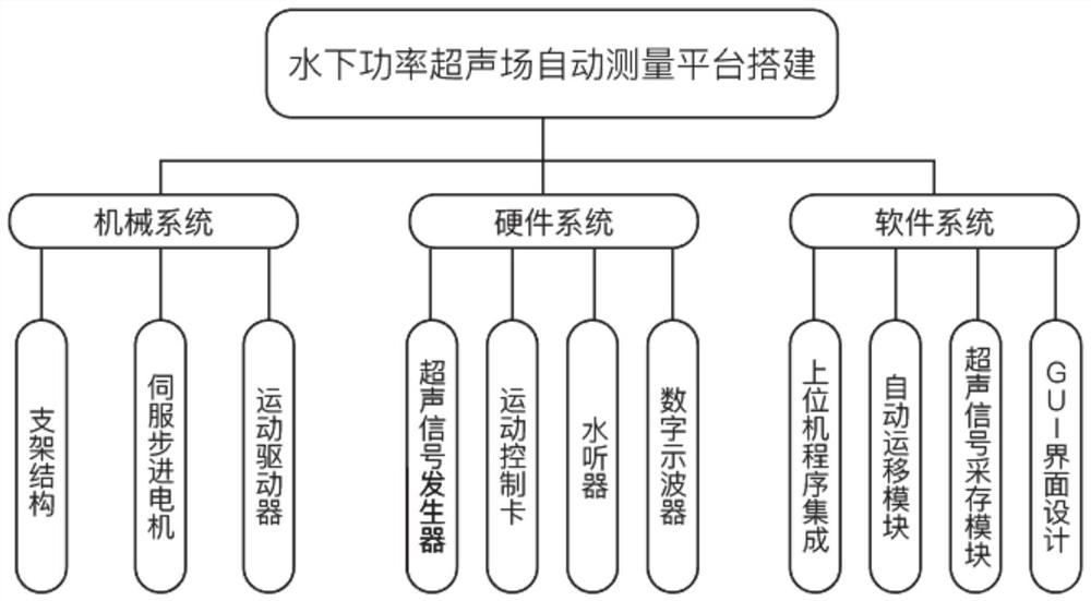
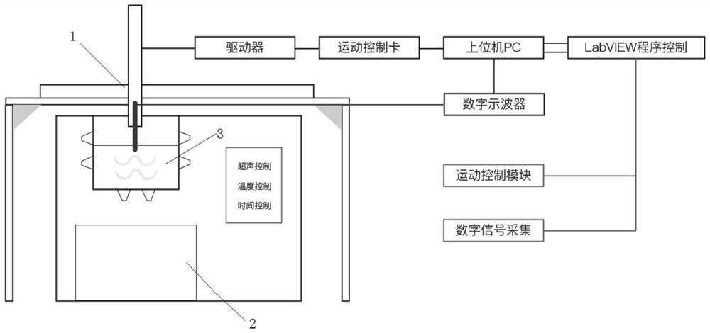
[0044] This embodiment provides an automatic measurement and visualization system for underwater ultrasonic cavitation field characteristics, such as figure 1As shown, it includes a sound field signal acquisition module, an automatic measurement platform 1, a control system, and a sound field visualization module. The sound field signal acquisition module is used to collect sound field signals; the sound field signal acquisition module is connected to the automatic measurement platform 1, and the sound field signal acquisition is driven by the automatic measurement platform 1. The module moves along the X-axis, Y-axis and Z-axis directions. The automatic measurement platform 1 is connected with a control system, and the control system is used to control the movement of the automatic measurement platform 1 . The sound field visualization module is connected with the signal acquisition module, and can analyze and process the sound field information.

[0045] Specifically, the s...

Embodiment 2

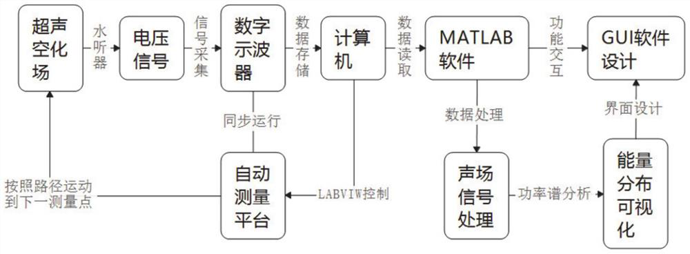
[0067] This embodiment provides a method for automatic measurement and visualization of underwater ultrasonic cavitation field characteristics, using the system described in Embodiment 1, such as figure 2 As shown, including: the hydrophone receives ultrasonic information and converts the ultrasonic information into a voltage signal; the voltage signal of the hydrophone is transmitted to a digital oscilloscope for storage. The computer (host computer) obtains the data information stored by the digital oscilloscope, processes the sound field signal, and realizes the visualization of energy distribution through power spectrum analysis.

[0068] Among them, the hydrophone can realize the automatic detection of rectangular and cylindrical ultrasonic fields driven by the automatic measurement platform. This embodiment plans the measurement path for the automatic detection of rectangular / cylindrical ultrasonic fields:

[0069] (1) Rectangular sound field such as Figure 8 Shown: Set...


PUM


Abstract

The invention discloses an underwater ultrasonic cavitation field characteristic automatic measurement and visualization system and method. According to the technical scheme, the underwater ultrasoniccavitation field characteristic automatic measurement and visualization system comprises a sound field signal acquisition module, an automatic measurement platform, a control system and a sound fieldvisualization module. The sound field signal acquisition module is used for acquiring sound field signals; the automatic measurement platform is connected with the sound field signal acquisition module and can drive the sound field signal acquisition module to move so as to realize automatic detection of a rectangular or cylindrical sound field; the control system is connected with the automaticmeasurement platform and used for controlling the movement of the automatic measurement platform; and the sound field visualization module is connected with the signal acquisition module and can analyze and process the sound field information. According to the invention, an underwater sound field can be accurately measured, and qualitative and quantitative characterization can be carried out on sound field parameters.

Description

technical field [0001] The invention relates to the field of sound field measurement, in particular to a system and method for automatic measurement and visualization of underwater ultrasonic cavitation field characteristics. Background technique [0002] Ultrasound has been used in many fields due to its high-quality properties such as good directionality, strong penetrability, and easy access, such as ultrasonic cleaning, ultrasonic sterilization, and ultrasonic welding. In recent years, the application of underwater power ultrasound has mainly focused on ultrasonic surface treatment, ultrasonic cleaning, sonochemistry, sewage treatment, etc. The effects of these applications are closely related to the properties of the underwater sound field. The characteristics of the ultrasonic field are measured and characterized. [0003] Existing measurement methods include: radiation force method, hydrophone method, optical fiber detection method, thin film corrosion method, liquid...

Claims


Application Information

Patent Timeline
Patent Type & Authority Applications(China)
IPC IPC(8): G01H3/00
CPCG01H3/00
Inventor 张宗波饶云龙王凯姚慧敏刘文港徐春玲姜琛
Owner CHINA UNIV OF PETROLEUM (EAST CHINA)
Learn More