Hydraulic control system of excavating device of cantilever tunneling machine

A technology of hydraulic control system and cantilever roadheader, which is applied to fluid pressure actuation system components, fluid pressure actuation devices, mechanical equipment, etc., and can solve problems such as limited excavation section, low excavation efficiency, and limited application range , to achieve the effect of improving hydraulic control precision and improving excavation efficiency

Pending Publication Date: 2020-12-11
CHINA RAILWAY ENGINEERING EQUIPMENT GROUP CO LTD
View PDF9 Cites 0 Cited by
  • Summary
  • Abstract
  • Description
  • Claims
  • Application Information

AI Technical Summary

Problems solved by technology

[0002] At present, the excavation section of the roadheader is basically circular. Although there are a few cases where special-shaped sections such as rectangles and horseshoes can be completed, these special-shaped sections are all used in the excavation of soft soil tunnels, which have not yet been seen in rock tunnel engineering. Once the excavation section of this type of roadheader is determined, it cannot be changed again during the application process. Its excavation shape is single and its application range is limited, so it is impossible to excavate any section.
And the existing cantilever roadheader such as the application number is CN201911269643.5, a kind of cantilever roadheader with a shoe and the cantilever roadheader of its construction method can only be excavated by the rotary cutter, the excavation resistance is large, and the excavation section is affected. limited, and the excavation efficiency is low, and the rotary cutter cannot be accurately controlled in real time. Therefore, it is necessary to develop a hydraulic control system that can excavate any section of the cantilever tunneling machine with variable diameter, so as to adapt to the precise excavation of tunnels with various sections.

Method used


Image

  • Hydraulic control system of excavating device of cantilever tunneling machine
  • Hydraulic control system of excavating device of cantilever tunneling machine
  • Hydraulic control system of excavating device of cantilever tunneling machine

Examples


Embodiment Construction

[0016] The following will clearly and completely describe the technical solutions in the embodiments of the present invention with reference to the accompanying drawings in the embodiments of the present invention. Obviously, the described embodiments are only some, not all, embodiments of the present invention. Based on the embodiments of the present invention, all other embodiments obtained by persons of ordinary skill in the art without making creative efforts belong to the protection scope of the present invention.

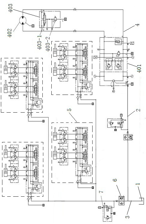
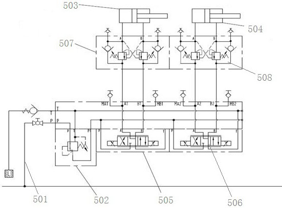
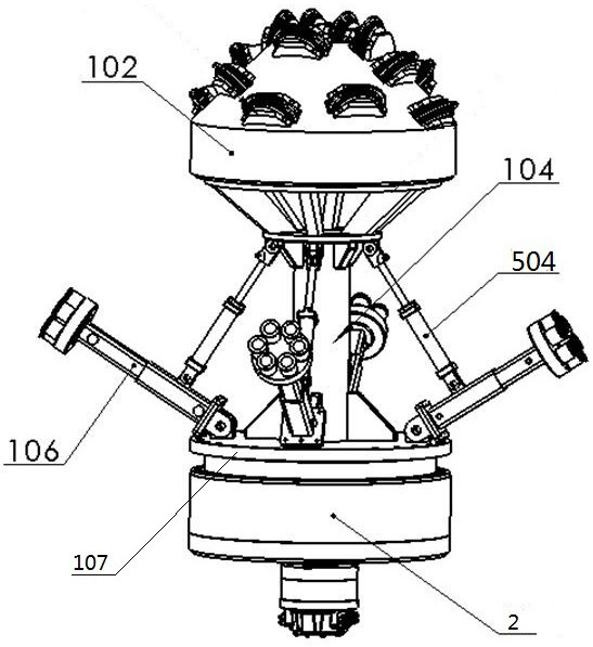
[0017] Such as figure 1 As shown, embodiment 1, a hydraulic control system of a cantilever roadheader excavation device, includes a connected constant pressure oil source 1 and a controller, and the controller is the control system of the entire system. The constant pressure oil source 1 is connected with a central oil passage 2 and a rotary cutting oil passage 3 , and the central oil passage 2 provides power for the rotation of the central cutter head 102 . ...


PUM


Abstract

The invention discloses a hydraulic control system of an excavating device of a cantilever tunneling machine. The hydraulic control system comprises a constant-pressure oil source and a controller which are connected with each other, the constant-pressure oil source is connected with a central oil path and a rotary cutting oil path, the central oil path is provided with a main driving hydraulic unit, the rotary cutting oil path is connected with N telescopic rotary cutting arm hydraulic units in parallel, and N is larger than or equal to 1; and a high-pressure filter and an energy accumulatorassembly are arranged on the rotary cutting oil path, and the main drive hydraulic unit and the telescopic rotary cutting arm hydraulic unit are both connected with the controller. The main driving hydraulic unit and the telescopic rotary cutting arm hydraulic unit form complete PID closed-loop control, the hydraulic control precision is improved, and excavation of various sections of a tunnel isachieved.

Description

technical field [0001] The invention relates to the technical field of cantilever roadheaders, in particular to a hydraulic control system of a cantilever roadheader excavation device. Background technique [0002] At present, the excavation section of the roadheader is basically circular. Although there are a few cases where special-shaped sections such as rectangles and horseshoes can be completed, these special-shaped sections are all used in the excavation of soft soil tunnels, which have not yet been seen in rock tunnel engineering. Once the excavation section of this type of roadheader is determined, it cannot be changed again during the application process. Its excavation shape is single, the application range is limited, and it is impossible to excavate any section. And the existing cantilever roadheader such as the application number is CN201911269643.5, a kind of cantilever roadheader with a shoe and the cantilever roadheader of its construction method can only be ...

Claims


Application Information

Patent Timeline
Patent Type & Authority Applications(China)
IPC IPC(8): F15B1/02F15B21/02F15B13/08F15B21/041E21D9/10
CPCF15B1/02F15B21/02F15B21/041F15B13/0807F15B13/086F15B13/085E21D9/108E21D9/1006F15B2211/6336F15B2211/6656
Inventor 叶蕾文勇亮贾连辉许顺海赵华卓普周李建斌姜礼杰钱豪
Owner CHINA RAILWAY ENGINEERING EQUIPMENT GROUP CO LTD
Why Eureka
Try Eureka