The structure of the incoming line of the socket
A socket and wire entry technology, which is applied to the parts of the connection device, coupling device, contact parts, etc., can solve the problems of low assembly efficiency of the incoming wire structure, inconvenient mass production, etc., to avoid assembly efficiency, facilitate mass production, The effect of meeting the assembly requirements
- Summary
- Abstract
- Description
- Claims
- Application Information
AI Technical Summary
Problems solved by technology
Method used
Image
Examples
Embodiment 1
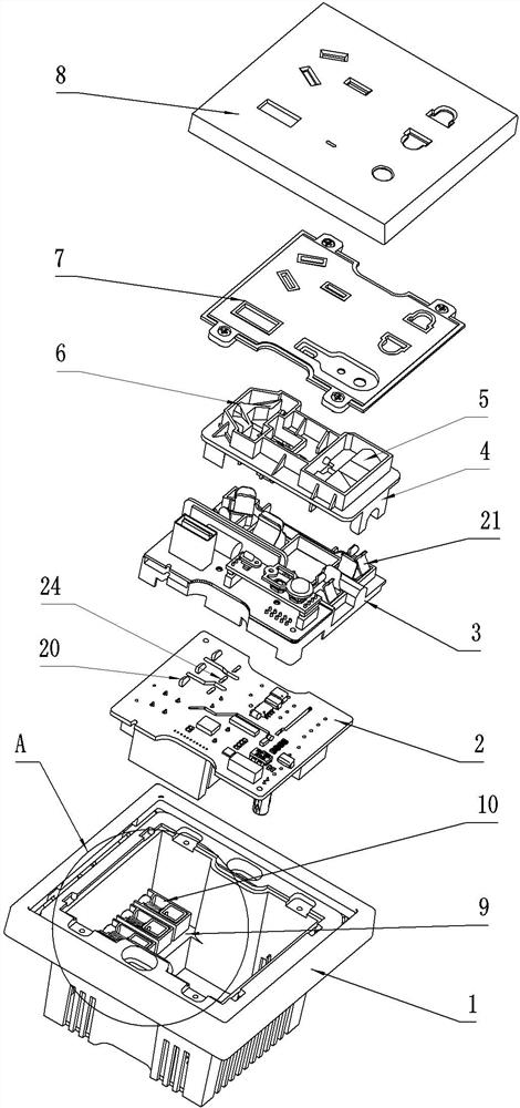
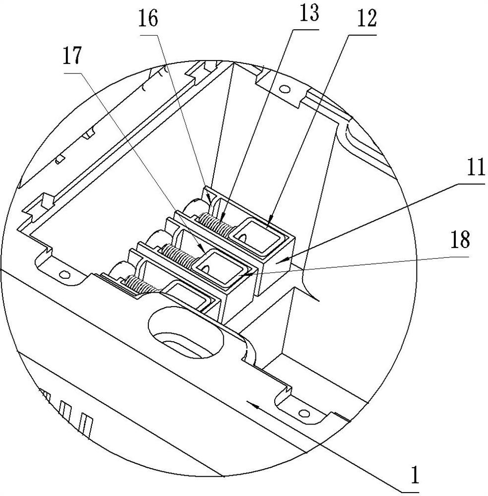
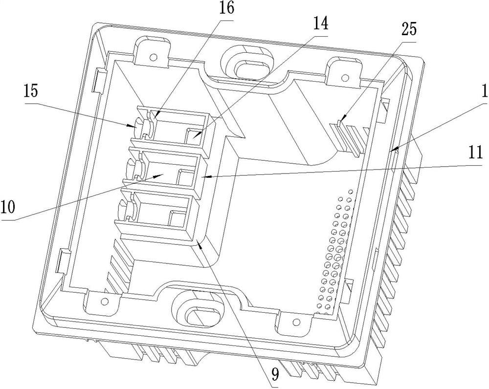
[0060] The wire entry structure of this socket is used such as figure 1 As shown in the socket, the socket includes a wall-embedded shell 1, and the embedded-wall shell 1 is the lower shell of the socket, which is used to be installed in the bottom box on the wall. The buried wall shell 1 is provided with a cavity, the opening of the cavity faces upwards, and a circuit board 2 , a lower bracket 3 and an upper bracket 4 are sequentially installed in the cavity. The upper bracket 4 is provided with a two-hole safety door 5 and a three-hole safety door 6 , and the two-hole safety door 5 and the three-hole safety door 6 are guided and assembled on the upper bracket 4 along the front and rear directions. The socket also includes a safety door gland 7 and a decorative cover 8 . The safety door gland 7 is fixed at the top opening of the embedded wall shell 1 by screws at four corners, so as to cover the internal components of the embedded wall shell 1 . The decorative cover 8 is the...
Embodiment 2
[0069] The difference between this embodiment and Embodiment 1 is that in Embodiment 1, the terminal connecting seat is formed by the circuit board 2 , while in this embodiment, the terminal connecting seat is a separator made of insulating material, and a plug-in spring is fixed on the separator. , the conductive contact piece 20 is fixed on the terminal connection seat, and is used for conductive connection with the plug-in spring piece on the partition. For the structure of the partition plate and the plug-in elastic sheet, reference may be made to the structure disclosed in CN208539253U in the background art.
Embodiment 3
[0071] The difference between this embodiment and Embodiment 1 is that in Embodiment 1, the locking screw 13 is inserted into the terminal installation groove 10 in the up-down direction, while in this embodiment, the locking screw 13 is along the extension direction of the terminal installation groove 10 One end is inserted into the terminal installation slot 10 , and then screwed to the wiring frame 12 in the terminal installation slot 10 . At this time, the operation port 15 on the embedded wall casing 1 for operating the locking screw 13 is larger than the diameter of the locking screw 13 .
[0072] In other embodiments, a cover plate may also be provided at the top opening of the terminal installation slot 10. After the wiring frame and the locking screws are installed, the cover plate is sealed into the terminal installation slot by means of snaps, screws, etc. At the same time, A plug-in port is provided on the cover plate, and the plug-in port is used for the insertion...
PUM
 Abstract
Description
Claims
Application Information
 - R&D
- Intellectual Property
- Life Sciences
- Materials
- Tech Scout
- Unparalleled Data Quality
- Higher Quality Content
- 60% Fewer Hallucinations
Browse by: Latest US Patents, China's latest patents, Technical Efficacy Thesaurus, Application Domain, Technology Topic, Popular Technical Reports.
© 2025 PatSnap. All rights reserved.Legal|Privacy policy|Modern Slavery Act Transparency Statement|Sitemap|About US| Contact US: help@patsnap.com


