
Fan coil forming machine

A technology of fan coil unit and forming machine, which is applied in the direction of heat exchange equipment, etc., can solve the problems of coil movement, affecting the winding and forming process, unable to ensure the same diameter of the coil, and achieve the same effect of the gap.

Inactive Publication Date: 2020-12-08
欧阳福鑫
View PDF8 Cites 2 Cited by
  • Summary
  • Abstract
  • Description
  • Claims
  • Application Information

AI Technical Summary

Problems solved by technology

[0004] (1) During the winding and forming process of the coil, the coil is wound by the rotation of the winding equipment itself, which cannot guarantee that the diameter of each coil is the same, and the distance between each coil is the same;
[0005] (2) During the winding and forming process of the coil, if any part of the coil is loose during winding, it will cause the coil to move, thus affecting the completion of the winding and forming process

Method used


Image

  • Fan coil forming machine
  • Fan coil forming machine
  • Fan coil forming machine

Examples


Embodiment Construction

[0030] The embodiments of the present invention will be described in detail below with reference to the accompanying drawings, but the present invention can be implemented in many different ways defined and covered by the claims.

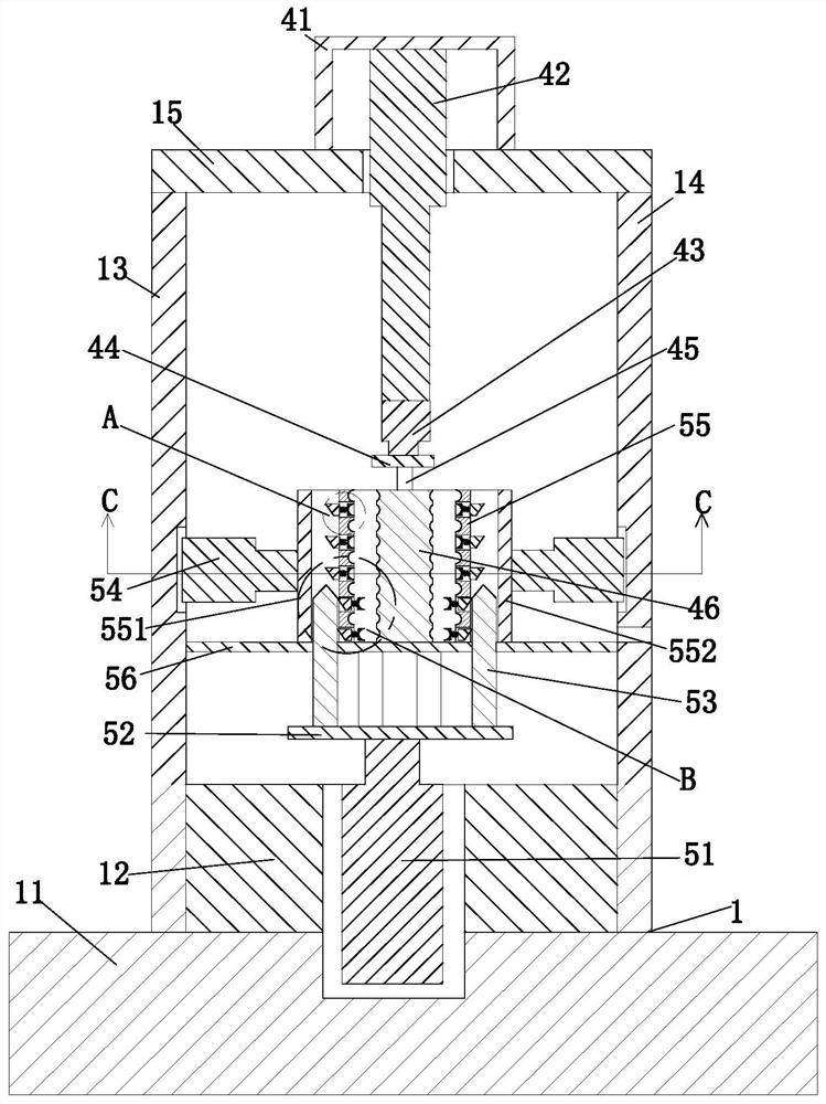
[0031] Such as Figure 1 to Figure 7 As shown, a fan coil forming machine includes a fixing seat 1, a mounting block 2, a pushing cylinder 3, a winding device 4 and a pressing device 5; The lower end is equipped with a push cylinder 3, the middle part of the upper end of the fixed seat 1 is equipped with a winding device 4, the lower end of the fixed seat 1 is symmetrically installed with the winding device 4, and the pressing device 5 is installed. The side is connected with the inner wall on the right side,

[0032] Described fixed seat 1 comprises base plate 11, rectangular block 12, left baffle plate 13, right baffle plate 14 and top plate 15, and the upper end middle part of base plate 11 is equipped with rectangular block 12, and rectangular ...


PUM


Abstract

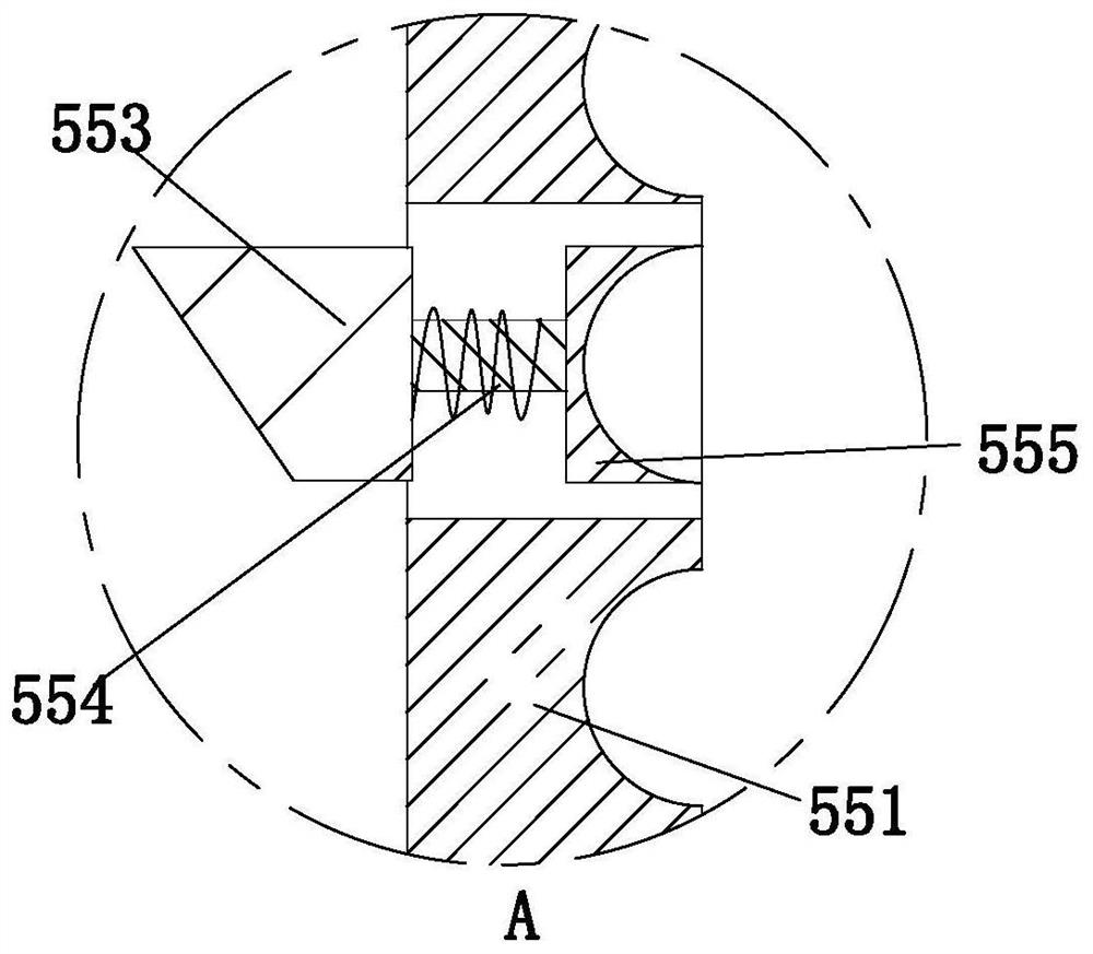
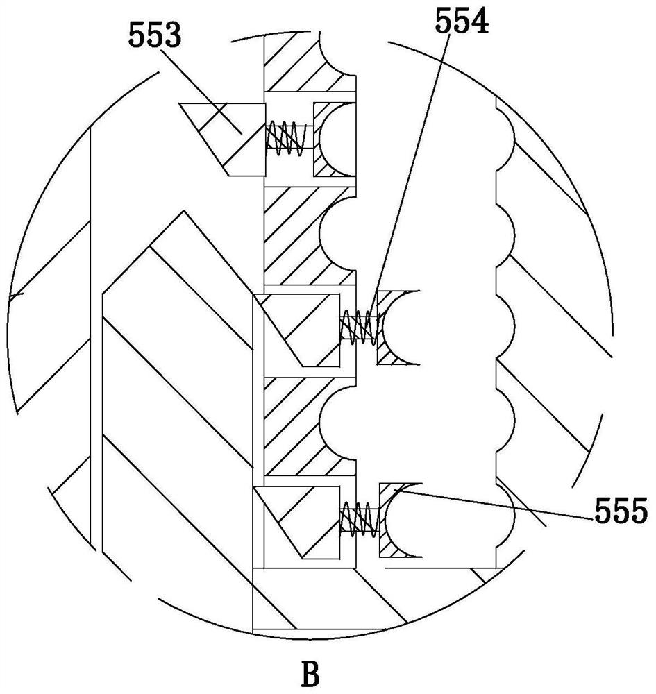
The invention relates to a fan coil forming machine comprising a fixing base, mounting blocks, pushing air cylinders, a winding device and abutting devices. The mounting blocks are mounted at the rearend of the fixing base in a bilateral symmetry manner, the pushing air cylinders are mounted at the lower ends of the mounting blocks, the winding device is mounted in the middle of the upper end ofthe fixing base, and the abutting devices are symmetrically mounted at the lower end of the fixing base and the winding device. According to the fan coil forming machine, a spiral groove is formed inthe outer wall of a positioning column of the winding device, one end of a manufactured coil pipe is fixed in the spiral groove through a fixing pipe, the wound and formed coil pipes are prevented from moving up and down, the wound and formed coil pipes abut against one another in sequence through clamping blocks of the abutting devices, and when the coil pipes are completely wound and formed,theclamping blocks move towards the middle to extrude and form the coil pipes, so that it is guaranteed that the winding diameters of the coil pipes are the same, and gaps between the coil pipes are thesame.

Description

technical field [0001] The invention relates to the field of fan coil processing, in particular to a fan coil forming machine. Background technique [0002] The fan coil unit is made of coiled tubes, usually used for cooling and heating. When chilled water or hot water flows through the coil tube, it exchanges heat with the air outside the tube, so that the air is cooled, dehumidified or heated. Adjust the air parameters in the room. [0003] Since the coiled pipe needs to be coiled and formed after it is manufactured, the following problems still commonly exist during coiling and forming: [0004] (1) During the winding and forming process of the coil, the coil is wound by the rotation of the winding equipment itself, which cannot guarantee that the diameter of each coil is the same, and the distance between each coil is the same; [0005] (2) During the winding and forming process of the coil, if any part of the coil is loose during winding, the coil will move, thereby a...

Claims


Application Information

Patent Timeline
Patent Type & Authority Applications(China)
IPC IPC(8): B21D11/06B21D11/22B21D53/06
CPCB21D11/06B21D11/22B21D53/06
Inventor 欧阳福鑫
Owner 欧阳福鑫
Learn More