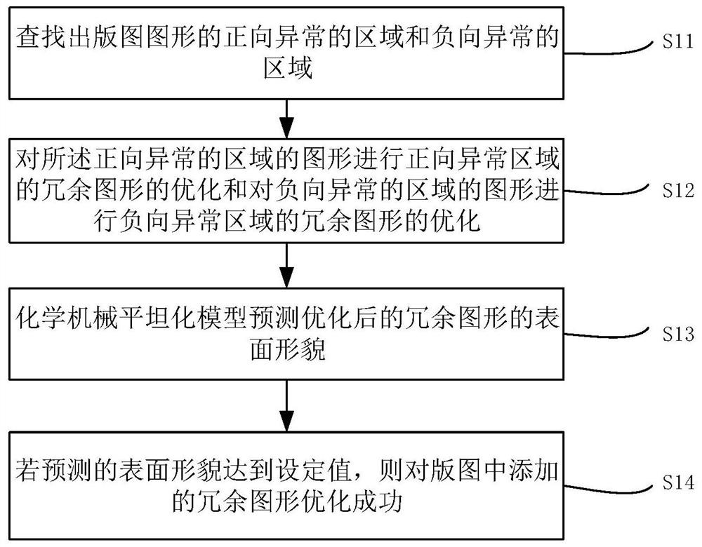
Method for optimizing redundant graphics
A technology of redundant graphics and optimization methods, which is applied in special data processing applications, instruments, electrical digital data processing, etc., can solve the problem of not considering the influence of the top surface topography of the underlying graphics, the initial graphics distribution of the layout is not the same, and cannot directly reflect Questions such as exact surface topography changes
- Summary
- Abstract
- Description
- Claims
- Application Information
AI Technical Summary
Problems solved by technology
Method used
Image

Examples
Embodiment Construction
[0043] The specific implementation manner of the present invention will be described in more detail below with reference to schematic diagrams. The advantages and features of the present invention will be more apparent from the following description. It should be noted that all the drawings are in a very simplified form and use imprecise scales, and are only used to facilitate and clearly assist the purpose of illustrating the embodiments of the present invention.
[0044] Hereinafter, the terms "first", "second", etc. are used to distinguish between similar elements, and are not necessarily used to describe a specific order or chronological order. It is to be understood that these terms so used are interchangeable under appropriate circumstances. Similarly, if a method described herein includes a series of steps, the order in which these steps are presented is not necessarily the only order in which these steps can be performed, and some described steps may be omitted and / or...
PUM
 Abstract
Description
Claims
Application Information
 - R&D
- Intellectual Property
- Life Sciences
- Materials
- Tech Scout
- Unparalleled Data Quality
- Higher Quality Content
- 60% Fewer Hallucinations
Browse by: Latest US Patents, China's latest patents, Technical Efficacy Thesaurus, Application Domain, Technology Topic, Popular Technical Reports.
© 2025 PatSnap. All rights reserved.Legal|Privacy policy|Modern Slavery Act Transparency Statement|Sitemap|About US| Contact US: help@patsnap.com