
Textile printing and dyeing equipment and using method

A technology for textile printing and dyeing and printing and dyeing equipment, which is applied in the processing of textile material equipment configuration, textile and papermaking, textile material processing, etc. Effect

Pending Publication Date: 2020-12-04
苏州云刚智能科技有限公司
View PDF7 Cites 4 Cited by
  • Summary
  • Abstract
  • Description
  • Claims
  • Application Information

AI Technical Summary

Problems solved by technology

[0004] One of the purposes of the present invention is to solve the problem that the surface of the cloth will be burned during singeing in the existing textile printing and dyeing equipment

Method used


Image

  • Textile printing and dyeing equipment and using method
  • Textile printing and dyeing equipment and using method
  • Textile printing and dyeing equipment and using method

Examples


Embodiment 1

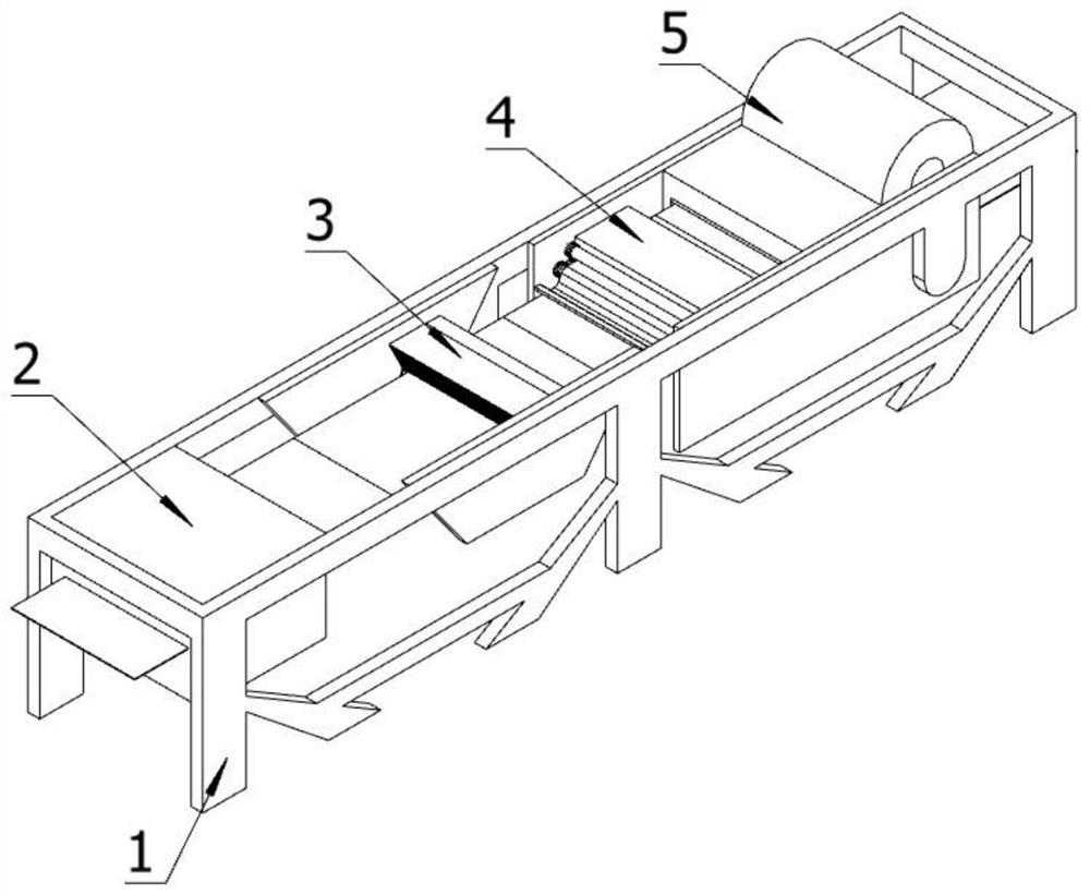
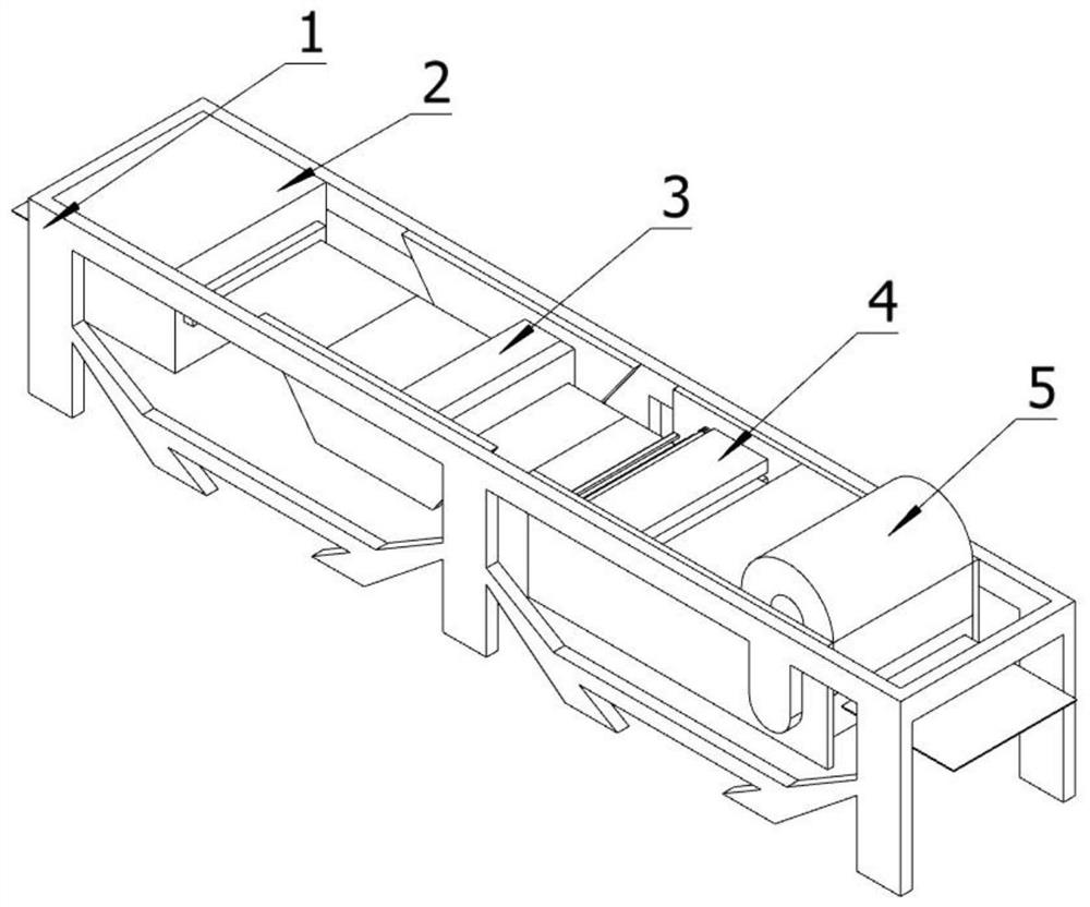
[0068] Such as figure 1 , 2 Shown, a kind of textile printing and dyeing equipment is characterized in that, comprises:

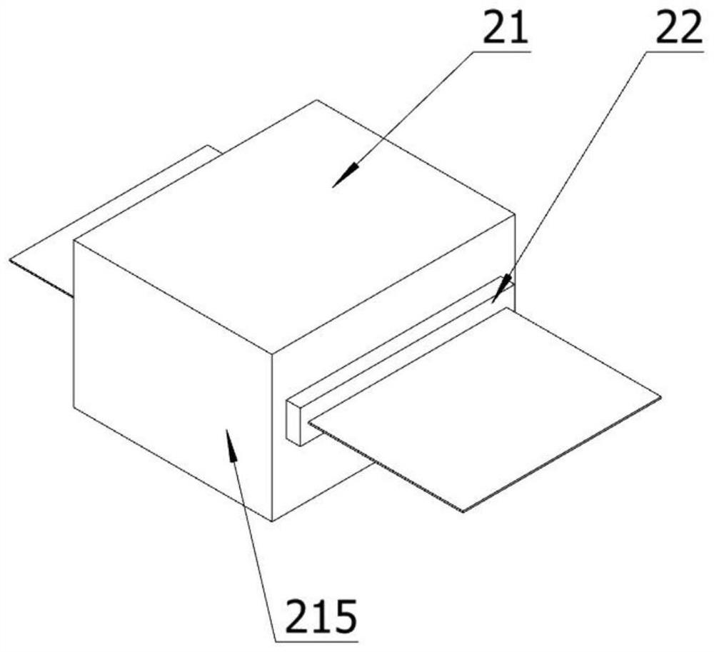
[0069] Bracket 1, the bracket 1 is set on the ground, the bracket 1 is provided with six supporting feet, a horizontal vertical plate is arranged between the supporting feet, a dehumidification mechanism 2 is arranged on the front end of the bracket 1, and the dehumidification mechanism 2 also includes : dehumidification equipment 21, dehumidification equipment 21 is connected to the inner two sides of support 1, dehumidification mechanism 2 is positioned at the front end of support 1, raising equipment 22, raising equipment 22 is connected to the rear end of dehumidification equipment 21, singeing mechanism 3, singeing mechanism 3 is connected to both sides inside the support 1, the singeing mechanism 3 is located at the middle front part of the support 1, the singeing equipment main body 32, the singeing equipment main body 32 is connected to the inner t...


PUM


Abstract

The invention discloses textile printing and dyeing equipment, and relates to the field of printing and dyeing. The textile printing and dyeing equipment comprises a bracket, a dehumidifying mechanism, a singeing mechanism, a sweeping wheel mechanism and a printing and dyeing mechanism. After cloth enters the dehumidifying mechanism, the cloth is tidied and dried, and fluff on the surface of the cloth is erected by static electricity; after the cloth enters the singeing mechanism, the fluff is blown out through front upper-layer hot air to improve the fluff erecting effect; the fluff is suckedby a suction port in a lower layer, coked and brought into a collecting box by an air suction port; the singed cloth enters the sweeping wheel mechanism, so that possibly remaining fluff coke balls or other impurities are swept away; and then the cloth is dyed by the printing and dyeing mechanism and is dried, so that the printing and dyeing effect is guaranteed.

Description

technical field [0001] The invention relates to the field of textiles, in particular to a textile printing and dyeing equipment and a use method. Background technique [0002] When the fabric is rubbed during the weaving process, many short and loose fibers are exposed on the surface of the yarn, and a layer of short fibers stands on the surface of the fabric. If the fabric is flattened, you can see this layer of fluff of different lengths along the cloth surface in front of your eyes. This layer of fluff not only affects the smoothness of the fabric and is easy to be contaminated with dust, but also produces various defects in the printing and dyeing process. [0003] Therefore, fabrics such as general cotton, hemp will carry out singeing treatment, and existing singeing machine often can slightly carbonize and burn the fabric surface when carrying out singeing treatment to cloth, not only cloth can be burned like this, and is in potential safety hazard. Contents of the ...

Claims


Application Information

Patent Timeline
IPC IPC(8): D06B1/02D06B23/20D06C9/02D06C15/02D06G1/00
CPCD06B1/02D06B23/205D06C9/02D06G1/00D06C15/02
Inventor 朱赟华旭亮顾卫忠王荣
Owner 苏州云刚智能科技有限公司
Learn More