
Blanking method of rotor wafer with boss

A boss and wafer technology is applied in the field of punching rotor discs with bosses, which can solve the problems of low punching efficiency and increased cost, and achieves the problem of processing efficiency and processing cost, and the processing cycle is short. , The effect of simple mold structure design

Pending Publication Date: 2020-12-04
HANGZHOU NEW HENGLI ELECTRONICS MACHINE MFG
View PDF0 Cites 0 Cited by
  • Summary
  • Abstract
  • Description
  • Claims
  • Application Information

AI Technical Summary

Problems solved by technology

[0003] In addition, in order to improve the utilization rate of materials, nesting is often used, but in order to prevent the rotor punch from rotating on the shaft, a keyway will be added in the shaft hole to position it with the shaft during design. Outside the chip, the other substrates often have two redundant keyway bosses, which need to be removed by adding a special process, not only the punching efficiency is not high, but also the cost is increased

Method used


Image

  • Blanking method of rotor wafer with boss
  • Blanking method of rotor wafer with boss
  • Blanking method of rotor wafer with boss

Examples


Embodiment Construction

[0030] The present invention will be further described below in conjunction with the accompanying drawings and embodiments.

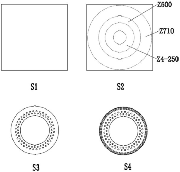
[0031] Please refer to Figure 1-Figure 7 , the punching method of the rotor disc with the boss includes the following steps:

[0032] S1: lower slice;

[0033] S2: Blanking;

[0034] S3: Punch the ventilation hole;

[0035] S4: Grooving and boss cutting.

[0036] In the step S1, the lower sheet of the slitting machine is used; in the step S2, a hydraulic press is used for blanking; in the step S3, a servo-driven high-speed notching machine is used to punch the ventilation holes; in the step S4, a mold is used for punching. trough shape.

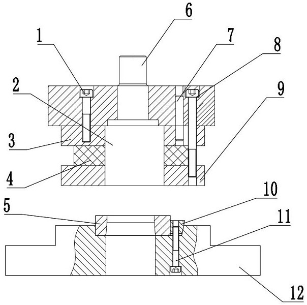
[0037] Described mold comprises upper mold base and lower mold base 12, and the bottom side of described upper mold base is equipped with fixed plate 3, and the bottom side of described fixed plate 3 is equipped with stripper plate 9, and described upper mold base is equipped with Convex mold 2, the top side of ...


PUM


Abstract

The invention provides a blanking method of a rotor wafer with a boss. The blanking method of the rotor wafer with the boss comprises the following steps that S1, a square wafer is discharged; S2, blanking is conducted; S3, a vent hole is punched; and S4, notching and boss cutting are conducted. Specifically, a strip-parting slitting cutter is used in the step S1 for discharging the square wafer,an oil press is used in the step S2 for blanking, a servo drive high-speed notching machine is used in the step S3 for punching the vent hole, and a die is used in the step S4 for notching. Accordingto the blanking method for the rotor wafer with the boss, a 7-shaped die structure is adopted, the die structure is simple in design, short in machining period and low in manufacturing cost, and therefore the redundant boss can be cut off and a groove shape can be machined at a time, one procedure is reduced compared with the prior art, and the problems of machining efficiency and machining cost are well solved.

Description

technical field [0001] The invention relates to the technical field of punching equipment, in particular to a punching method of a rotor disc with a boss. Background technique [0002] In the motor manufacturing industry, there are many specifications of the rotor punching sheet of the motor. Except for the groove size and the number of slots, the other sizes of the rotor sheet of the same type are the same. Improve the processing efficiency, that is, the rotor shaft hole, ventilation hole, and groove shape are formed by one-time blanking. Most of the time, in order to reduce the investment cost of the mold, according to the process, it is necessary to punch the substrate first, and then use a single-slot punching die on a high-speed punching machine Punch groove shape. [0003] In addition, in order to improve the utilization rate of materials, nesting is often used, but in order to prevent the rotor punch from rotating on the shaft, a keyway will be added in the shaft h...

Claims


Application Information

Patent Timeline
Patent Type & Authority Applications(China)
IPC IPC(8): B21D28/14B21D35/00H02K15/02
CPCB21D28/14B21D35/001H02K15/02
Inventor 周淼吴显明郑华
Owner HANGZHOU NEW HENGLI ELECTRONICS MACHINE MFG
Learn More