
Control method, device and electronic equipment for pod with multi-layer frame

A technology of multi-layer framework and control method, which is applied in the direction of control using feedback, mechanical equipment, machine/stand, etc., can solve the problems of imaging quality influence of imaging equipment, disturbance of the inner frame of the pod, etc., to avoid geometric constraints, The effect of improving rotation accuracy and reducing the effect of image quality

Active Publication Date: 2022-03-25
GUANGZHOU KEII ELECTRO OPTICS TECH
View PDF7 Cites 0 Cited by
  • Summary
  • Abstract
  • Description
  • Claims
  • Application Information

AI Technical Summary

Problems solved by technology

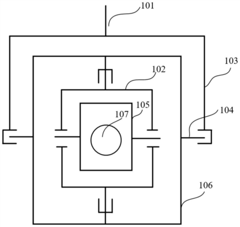
[0003] In practice, it is found that when the traditional control method controls the attitude rotation of the pod with a multi-layer frame, it usually directly controls the rotation of the outer frame of the pod (that is, the outer azimuth frame and the outer pitch frame) to realize the attitude rotation of the entire pod. However, due to the geometric constraints between the multi-layer frames, the rotation of the outer frame of the pod will disturb the inner frame of the pod (ie, the inner azimuth frame and the inner pitch frame), so that the imaging equipment set on the inner frame of the pod The image quality of the

Method used


Image

  • Control method, device and electronic equipment for pod with multi-layer frame
  • Control method, device and electronic equipment for pod with multi-layer frame
  • Control method, device and electronic equipment for pod with multi-layer frame

Examples


Embodiment Construction

[0051] The following will clearly and completely describe the technical solutions in the embodiments of the present application with reference to the accompanying drawings in the embodiments of the present application. Obviously, the described embodiments are only a part of the embodiments of the present invention, not all of them. Based on the embodiments of the present invention, all other embodiments obtained by persons of ordinary skill in the art without making creative efforts belong to the protection scope of the present invention.

[0052] It should be noted that the terms "first", "second", "third" and "fourth" in the specification and claims of the present invention are used to distinguish different objects, rather than to describe specific order. The terms "comprising" and "having" and any variations thereof in the embodiments of the present application are intended to cover a non-exclusive inclusion, for example, a process, method, system, product or device compris...


PUM


Abstract

The embodiment of the present application relates to the field of equipment control technology, and discloses a control method, device and electronic equipment for a pod with a multi-layer frame. The pod at least includes: an inner azimuth frame, an outer azimuth frame, an inner pitch frame and an outer pitch frame frame, the outer azimuth frame and the outer pitch frame are used to adjust the attitude of the pod, the inner azimuth frame and the inner pitch frame are used to set the imaging device, and the method includes: controlling the rotation of the inner azimuth frame and the inner pitch frame according to the received control command; And in the process of controlling the rotation of the inner azimuth frame and the inner pitch frame, measuring the first angle difference between the inner azimuth frame and the outer azimuth frame, and measuring the second angle difference between the inner pitch frame and the outer pitch frame; and then according to The first angle difference adjusts the outer orientation frame to align with the inner orientation frame, and adjusts the outer pitch frame to align with the inner pitch frame according to the second angle difference. By implementing the embodiment of the present application, the influence of the rotation of the pod on the imaging quality of the imaging device can be reduced.

Description

technical field [0001] The invention relates to the technical field of equipment control, in particular to a control method, device and electronic equipment for a gondola with a multi-layer frame. Background technique [0002] A pod with a multi-layer frame is usually composed of an inner azimuth frame connected with an azimuth axis, an outer azimuth frame, and a pitch axis connected with an inner pitch frame and an outer pitch frame. Used as a carrier for most imaging equipment. [0003] In practice, it is found that when the traditional control method controls the attitude rotation of the pod with a multi-layer frame, it usually directly controls the rotation of the outer frame of the pod (that is, the outer azimuth frame and the outer pitch frame) to realize the attitude rotation of the entire pod. However, due to the geometric constraints between the multi-layer frames, the rotation of the outer frame of the pod will disturb the inner frame of the pod (ie, the inner azi...

Claims


Application Information

Patent Timeline
Patent Type & Authority Patents(China)
IPC IPC(8): F16M11/12F16M11/18G05D3/12B64D47/08
CPCF16M11/123F16M11/18G05D3/12B64D47/08
Inventor 吴奇文赵勇汪洋
Owner GUANGZHOU KEII ELECTRO OPTICS TECH
Learn More