An unmanned surveying vessel for marine topographic mapping
A technology of terrain surveying and surveying ships, which is applied to surveying devices, surveying and navigation, special-purpose ships, etc., can solve problems such as unguaranteed safety, and achieve strong operability, high safety, and good surveying and mapping effects
- Summary
- Abstract
- Description
- Claims
- Application Information
AI Technical Summary
Problems solved by technology
Method used
Image

Examples
Embodiment 1
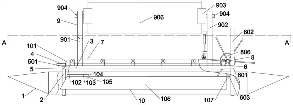
[0023] like Figure 1-Figure 2 As shown, in an embodiment of the present invention, an unmanned surveying vessel for marine topographical surveying and mapping includes two symmetrical cylindrical inflatable rubber bases 1, and the cylindrical inflatable rubber base 1 is covered with iron hoops 2 in front A connecting plate 3 is connected between the iron hoops 2, the left end of the connecting plate 3 is connected with a terrain detector 4, and a front bridge plate 5 is connected between the iron hoops 2 at the left ends of the two cylindrical inflatable rubber bases 1, A rear bridge plate 6 is connected between the iron hoop 2 at the right end of the two cylindrical inflatable rubber bases 1, and a conveyor belt drive mechanism 7 is connected between the rear bridge plate 6 and the front bridge plate 5. The conveyor belt drives The mechanism 7 is connected with a water wheel device 8 , a solar energy shrinking and stretching device 9 is arranged above the conveyor belt drivi...
Embodiment 2
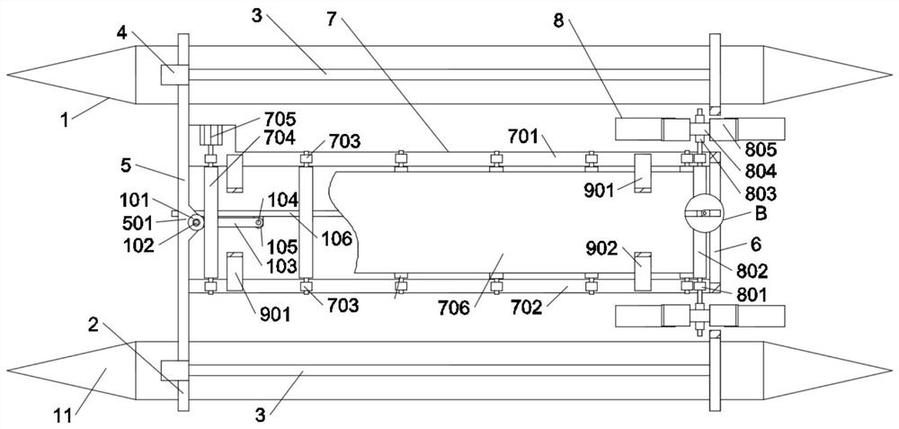
[0026] like Figure 1-Figure 2 As shown, in the embodiment of the present invention, the conveyor belt drive mechanism 7 includes a first mounting frame 701 and a second mounting frame 702, and the first mounting frame 701 and the second mounting frame 702 are symmetrically provided with a plurality of uniformly distributed Each pair of the first roller seats 703 is provided with a first belt roller 704, and the first belt roller 704 on the far left is connected to a first motor 705, the first belt roller 704 A rough-surfaced belt 706 is connected to the roller 704 , and the first belt roller 704 on the far right squeezes the water wheel device 8 tightly.
[0027] In the embodiment of the present invention, the transmission principle: the first motor 705 drives the leftmost first belt roller 704, the belt 706 and other first belt rollers 704 follow; on the one hand, the rightmost first belt roller 704 The belt 706 is sandwiched between the second belt roller 802 on the water ...
Embodiment 3
[0029] like Figure 1-Figure 2 As shown, in the embodiment of the present invention, the water wheel device 8 includes a pair of second roller seats 801 located on the first mounting bracket 701 and the second mounting bracket 702, and the second roller seats 801 are mounted on the second roller seats 801. There is a second belt roller 802, the shafts at both ends of the second belt roller 802 are connected with shaft sleeves 803, an outer ring 804 is sleeved on the outer side of the shaft sleeve 803, and the outer ring 804 and the shaft sleeve 803 are connected with A number of reinforcing rib plates 806, and a number of water-repelling paddles 805 are evenly distributed around the outer ring of the outer ring 804.
[0030] In the embodiment of the present invention, advancing and retreating: the second belt roller 802 rotates, the shaft sleeves 803, the outer ring 804, the reinforcing rib plate 806 and the water-repelling paddle 805 on both sides rotate, and the water-repell...
PUM
 Abstract
Description
Claims
Application Information
 - R&D
- Intellectual Property
- Life Sciences
- Materials
- Tech Scout
- Unparalleled Data Quality
- Higher Quality Content
- 60% Fewer Hallucinations
Browse by: Latest US Patents, China's latest patents, Technical Efficacy Thesaurus, Application Domain, Technology Topic, Popular Technical Reports.
© 2025 PatSnap. All rights reserved.Legal|Privacy policy|Modern Slavery Act Transparency Statement|Sitemap|About US| Contact US: help@patsnap.com