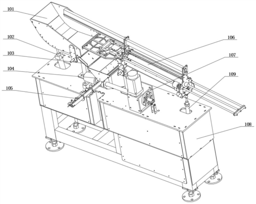
A fully automatic rod production equipment

A kind of production equipment, fully automatic technology, applied in metal processing equipment, measuring/indicating equipment, manufacturing tools, etc., can solve the problems of non-universal production, high defective rate, dependence on labor, etc.

Active Publication Date: 2022-06-24
包斌华
View PDF9 Cites 0 Cited by
  • Summary
  • Abstract
  • Description
  • Claims
  • Application Information

AI Technical Summary

Problems solved by technology

[0005] Aiming at the problems existing in the prior art, the purpose of the present invention is to provide a fully automatic rod production equipment, which has the advantages of scientific and reasonable structure, high work efficiency, low operation cost and long service life, and solves the problem of Manually operated punch processing methods, only a few enterprises have adopted semi-automatic assembly production equipment with manually placed steel handles. The reason for this is that automatic feeding of processing materials is a major problem in the industry. Steel balls and springs can still be automatically fed by traditional methods. However, the feeding of smooth surface materials such as steel handles is currently a difficult problem in automatic feeding. In addition, the existing semi-automatic assembly equipment can automatically assemble springs and steel balls, but the assembly of steel handles not only relies on manual work, but also requires the length Different products of the same model (steel handle diameter) cannot be produced universally. When producing workpieces of different lengths, the conveyor belt needs to be replaced. The essence is to replace the one-to-one corresponding fixtures, which will increase the cost of factory equipment and management. , At present, the assembly and production of adapters on the market are all manually inspected for the quality of finished products. In view of the current market situation, the labor cost of the factory is high, and the inspection of finished products is done manually, resulting in a high rate of defective products.

Method used


Image

  • A fully automatic rod production equipment
  • A fully automatic rod production equipment
  • A fully automatic rod production equipment

Examples


Embodiment Construction

[0044] The technical solutions in the embodiments of the present invention will be clearly and completely described below with reference to the accompanying drawings in the embodiments of the present invention; obviously, the described embodiments are only a part of the embodiments of the present invention, not all of the embodiments. The embodiments of the present invention, and all other embodiments obtained by those of ordinary skill in the art without creative work, fall within the protection scope of the present invention.

[0045] In the description of the present invention, it should be noted that the orientations or positional relationships indicated by the terms "upper", "lower", "inner", "outer", "top / bottom", etc. are based on the orientations shown in the drawings or The positional relationship is only for the convenience of describing the present invention and simplifying the description, rather than indicating or implying that the indicated device or element must ...


PUM


Abstract

The invention discloses a fully automatic post production equipment, which belongs to the field of post production. A fully automatic post production equipment includes: a steel handle automatic feeding module, a steel handle placement module, a steel handle hole finding module, a defective Steel handle rejection module, spring automatic feeding and detection module, steel ball automatic feeding and detection module, automatic clamping bottom bracket module, pressing module, finished product quality inspection module and finished product flow direction control module, the steel handle automatic feeding module includes basic The base is provided with a base on the front of the base. In the present invention, through the non-destructive screening of the surface of the steel handle, and the hole position can be identified, the material can be supplied efficiently and orderly; the stable single material supply of the spring can be detected in place and the alarm can be given for lack of material; the stable single material supply of the steel ball can be carried out , can detect in place and can alarm when there is a lack of material; the same model (steel handle diameter) with different lengths can be used for general production; the quality inspection of the product after processing can be carried out, and qualified products and unqualified products can be separated.

Description

technical field [0001] The invention relates to the field of post production, in particular to a fully automatic post production equipment. Background technique [0002] The hand-held socket tool is a general-purpose tool with a wide range of applications. It is simple and convenient to operate, and has higher work efficiency than other hand-held tools. It can especially solve the difficult operation of ordinary tools in some special spaces. Widely used in all walks of life. [0003] For the assembly and production of post in the hand tool manufacturing industry, the method of manual operation of punching machine processing is currently widely used. Only a few companies have adopted semi-automatic assembly production equipment that manually places steel handles. The automatic feeding of processing materials is a major industry in the industry. The problem is that steel balls and springs can still be automatically fed by traditional methods, but the supply of smooth surface ...

Claims


Application Information

Patent Timeline
Patent Type & Authority Patents(China)
IPC IPC(8): B23P21/00B23Q3/08B23Q7/14B23Q17/00
CPCB23P21/004B23Q3/082B23Q7/14B23Q17/006
Inventor 包斌华
Owner 包斌华
Why Eureka
Try Eureka