
Implant

A technology for implants and external parts, applied in the field of implants, can solve problems such as confusion, damage to screw joints, damage to implants, etc.

Pending Publication Date: 2020-11-27
阿斯卡拉波股份有限公司
View PDF11 Cites 0 Cited by
  • Summary
  • Abstract
  • Description
  • Claims
  • Application Information

AI Technical Summary

Problems solved by technology

However, in any case it is possible to get confused and tighten the nuts with an excessive tightening torque
In the worst case, this can lead to damage to the screw joint and thus to the entire implant
In particular, implant fracture may occur immediately or at a later time in the area of ​​the screw joint

Method used


Image

  • Implant
  • Implant
  • Implant

Examples


Embodiment Construction

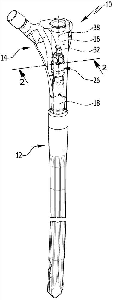
[0079] figure 1 An implant in the form of a revision stem of a hip endoprosthesis for insertion into the femoral cavity is shown in exemplified by reference number 10 .

[0080] Implant 10 includes a first implant portion 12 and a second implant portion 14 . The first implant part 12 forms a proximal shaft section with a longitudinal perforation 16 .

[0081] The second implant part 14 forms a shank extension to the first implant part 12 and comprises a coupling section 18 which is inserted distally into the longitudinal perforation 16 .

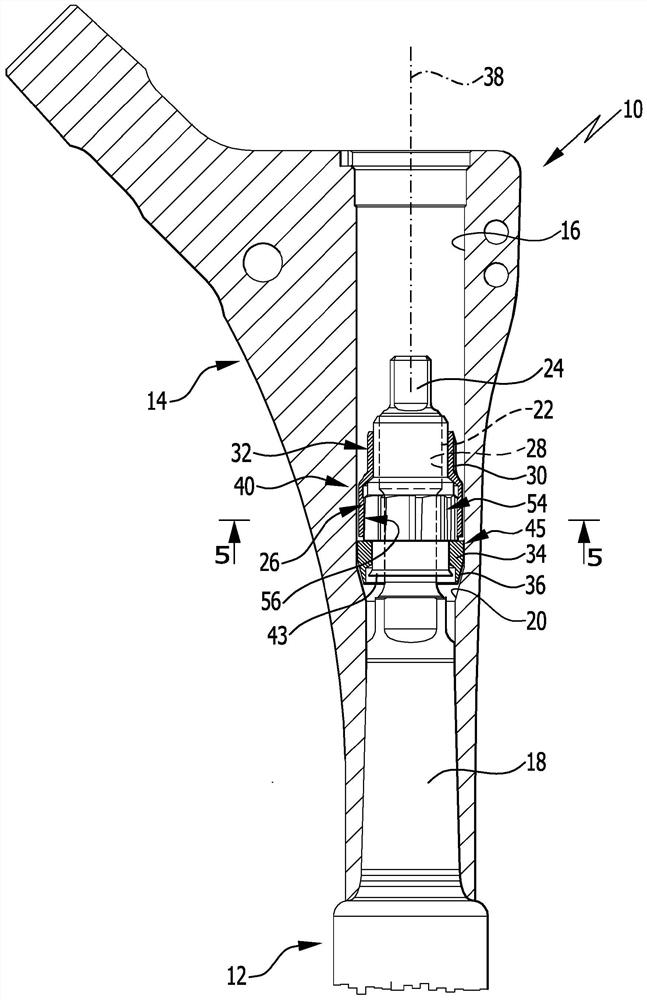
[0082] The inner cross section of the longitudinal perforation 16 tapers in cross section from the proximal end in the distal direction in the region of the shoulder 20 .

[0083] To connect the implant parts 12 and 14 , an external threaded section 22 is formed on the coupling section 18 . The externally threaded section 22 follows the proximal end 24 of the coupling section 18 , which is configured as a quadrangular shape.

[0084] Fur...


PUM


Abstract

The invention relates to an implant with a first implant part and with a second implant part, wherein the first implant part and the second implant part are connected to each other in a connection position via a screw connection comprising a nut, wherein the nut is configured in the form of a medical-type nut which defines a longitudinal axis and has an inner thread and a polygonal outer shape. Inorder to improve the implant such that the nut can be easily and safely tightened with a predefined tightening torque, it is proposed that the nut comprises at least one inner part and at least one outer part surrounding the inner part at least partially, in particular completely or substantially completely, that the at least one inner part comprises the inner thread, that the at least one outerpart comprises the polygonal outer shape, that the nut comprises a torque limiter which is configured in such a way that, if a torque acting on the at least one outer part in a tightening rotation direction is less than a limit torque, the at least one outer part and the at least one inner part are non-rotatable relative to each other in the tightening rotation direction, and that, if a torque acting on the at least one outer part in the tightening rotation direction at least corresponds to the limit torque, the at least one outer part and the at least one inner part are rotatable relative toeach other in the tightening rotation direction, and that the at least one inner part and the at least one outer part are coupled non-releasably to each other.

Description

technical field [0001] The invention relates to an implant having a first implant part and a second implant part, wherein the first and the second implant part are connected to each other in a connection position via a screw connection comprising a nut , wherein the nut is constructed in the form of a medical nut defining a longitudinal axis and having an internal thread and a polygonal shape. [0002] Additionally, a medical nut is described below that defines a longitudinal axis and has internal threads and a polygonal shape. Background technique [0003] Implants comprising more than two implant parts are also referred to as modular implants. In order to connect the implant parts of a modular implant to one another, it is known to use screw connections. For example, a pin section provided with an external thread can be formed on the first implant part, which pin section passes through a perforation in the second implant part. It is thus possible to screw the nut onto t...

Claims


Application Information

Patent Timeline
Patent Type & Authority Applications(China)
IPC IPC(8): A61F2/32
CPCA61F2/36A61F2/367A61F2002/3674A61F2002/30558A61F2002/30884
Inventor 托马斯·绍尔埃西希
Owner 阿斯卡拉波股份有限公司
Learn More