
Aerial operation robot for power transmission line maintenance

A technology for operating robots and transmission lines, applied in the direction of overhead lines/cable equipment, etc., can solve problems such as line tripping, impact on line transmission performance, and insufficient efficiency, and achieve the effects of reducing the degree of disturbance, good cutting effect, and improving accuracy

Active Publication Date: 2020-11-27
HUNAN UNIV
View PDF8 Cites 3 Cited by
  • Summary
  • Abstract
  • Description
  • Claims
  • Application Information

AI Technical Summary

Problems solved by technology

[0002] Transmission line obstacles are an important hidden danger that affects the safe and stable operation of the power grid, and floating objects are the most common type of obstacles, and their locations are unpredictable, especially in coastal areas. Due to the impact of typhoons, advertising banners and plastics on the ground Domestic garbage such as film is easily blown up and entangled on the transmission line, which can easily cause line tripping and affect the stable operation of the power grid
At the same time, the wide variety of floating objects and their wide distribution also bring great labor intensity and inconvenience to the grid inspection staff.
[0003] The current cleaning of floating objects mainly relies on manual cleaning or the use of unmanned aerial vehicles and flame-throwing devices to incinerate the floating objects on the transmission line. Fixed-point removal has the disadvantages of insufficient efficiency and high safety risks, while the way of UAV plus flamethrowing device has a high risk factor, and there will be residual residue on the transmission line, which will have a certain impact on the transmission performance of the line. The combustibles are likely to cause forest fires under the influence of strong winds

Method used


Image

  • Aerial operation robot for power transmission line maintenance
  • Aerial operation robot for power transmission line maintenance
  • Aerial operation robot for power transmission line maintenance

Examples


Embodiment 1

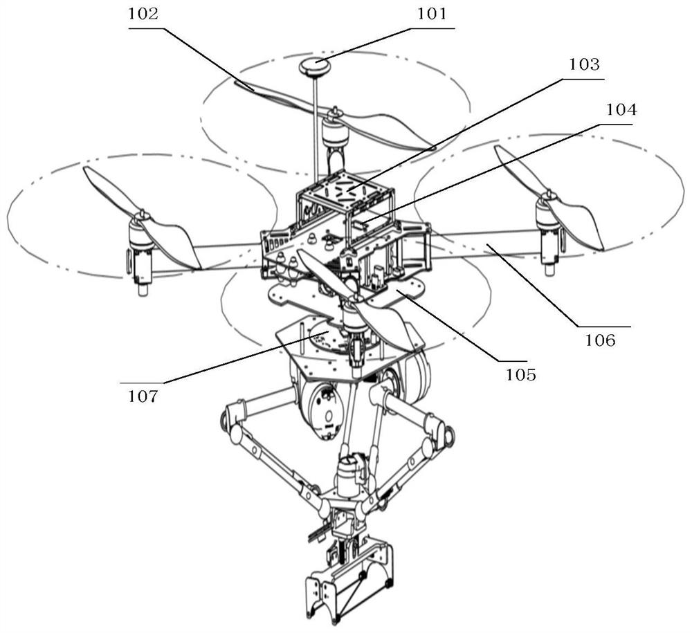
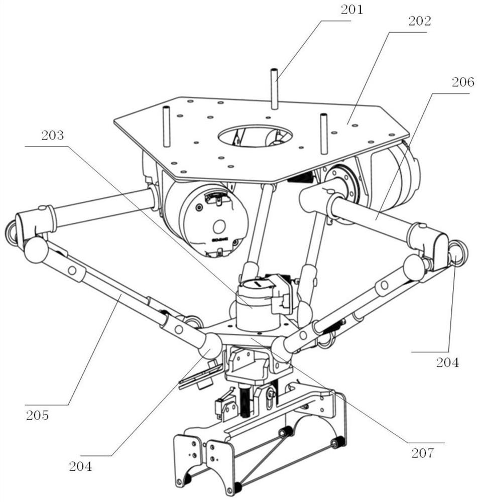
[0034] Such as figure 1 As shown, an aerial robot for power transmission line maintenance provided by Embodiment 1 of the present invention includes a multi-rotor UAV platform that provides flight power for the aerial robot, and a four-degree-of-freedom Delta parallel connection that dynamically compensates for UAV attitude changes. Mechanism, cutting operation mechanism for floating removal.

[0035] In this embodiment, the multi-rotor UAV platform includes four wings 102, a frame 106, a GPS device 101, a flight controller, a power supply module, and an onboard computer module. The wings 102 are installed on the outermost end of the frame 106, and the rotation of the wings 102 can provide lift for the aerial work robot, and the four sets of wings 102 are respectively distributed at 90 degrees.

[0036] The flight controller is the control center of the multi-rotor UAV. It is installed on the carbon fiber mounting plate No. 2, 104, and the onboard computer module is installed...


PUM


Abstract

The invention discloses an aerial operation robot for power transmission line maintenance, which comprises an unmanned aerial vehicle platform, a Delta parallel mechanism and a cutting operation mechanism, wherein the Delta parallel mechanism is fixed below the unmanned aerial vehicle platform, and the cutting operation mechanism is fixed at the tail end of the Delta parallel mechanism; the cutting operation mechanism at least comprises a clamping mechanism supporting plate, a clamping mechanism and an electric heating wire; the clamping mechanism is fixed to the clamping mechanism supportingplate, a containing space is formed in the clamping mechanism and used for containing a power transmission line, and the electric heating wire is fixed to the clamping mechanism and transversely penetrates through the containing space. The aerial operation robot provided by the invention can cut off the floating hanging object from the upper side; since the electric heating wire directly cuts offthe connection point of the floating hanging object and the power transmission line, the situation that residues are left does not exist, and the cutting effect is better.

Description

technical field [0001] The invention belongs to the technical field of transmission line foreign matter treatment, and in particular relates to an aerial work robot used for transmission line maintenance. Background technique [0002] Transmission line obstacles are an important hidden danger that affects the safe and stable operation of the power grid, and floating objects are the most common type of obstacles, and their locations are unpredictable, especially in coastal areas. Due to the impact of typhoons, advertising banners and plastics on the ground Domestic garbage such as film is easily blown up and entangled on the transmission line, which can easily cause line tripping and affect the stable operation of the power grid. At the same time, the wide variety of hanging objects and their wide distribution also bring great labor intensity and inconvenience to the grid inspection staff. [0003] The current cleaning of floating objects mainly relies on manual cleaning or ...

Claims


Application Information

Patent Timeline
Patent Type & Authority Applications(China)
IPC IPC(8): H02G1/02
CPCH02G1/02
Inventor 钟杭王耀南李玲缪志强
Owner HUNAN UNIV
Learn More