
Connecting device for stranding machine

A connecting device and stranding machine technology, which is applied in the manufacture of electrical components, circuits, cables/conductors, etc., can solve the problems of high maintenance rate, collapse of the cradle, easy wear of bridge gear drive shafts and bearings, etc., and improve the service life , Reduce the effect of direct wear

Inactive Publication Date: 2020-11-27
CHONGQING TAISHAN CABLE
View PDF8 Cites 0 Cited by
  • Summary
  • Abstract
  • Description
  • Claims
  • Application Information

AI Technical Summary

Problems solved by technology

Due to the high utilization rate of the equipment, the three strands are all driven by gears, and the transmission shafts and bearings of the bridge gears are easy to wear, and the maintenance rate is high. However, the original design of the bridge gear shafts of the manufacturer has defects. During use, the gear shafts cannot Locking, during high-speed operation, the gear shaft is loose, and there is a hidden danger of collapse of the cradle, which cannot be produced safely
On the other hand, the installation space is limited, it is difficult to maintain during the maintenance process, and it is extremely inconvenient to disassemble and install gears

Method used


Image

  • Connecting device for stranding machine
  • Connecting device for stranding machine
  • Connecting device for stranding machine

Examples


Embodiment Construction

[0020] The present invention will be further described below in conjunction with the accompanying drawings and embodiments. It should be noted that in the description of the present invention, the terms "upper", "lower", "left", "right", "inner", "outer" etc. The indicated orientation or positional relationship is based on the orientation or positional relationship shown in the drawings, and is only for the convenience of describing the present invention and simplifying the description, rather than indicating or implying that the referred device or element must have a specific orientation or in a specific way construction and operation, therefore, should not be construed as limiting the invention. The terms "first", "second", "third", etc. are used for descriptive purposes only and should not be construed as indicating or implying relative importance.

[0021] In the description of the present invention, it should be noted that unless otherwise specified and limited, the terms...


PUM

PropertyMeasurementUnit
diameteraaaaaaaaaa
lengthaaaaaaaaaa

Abstract

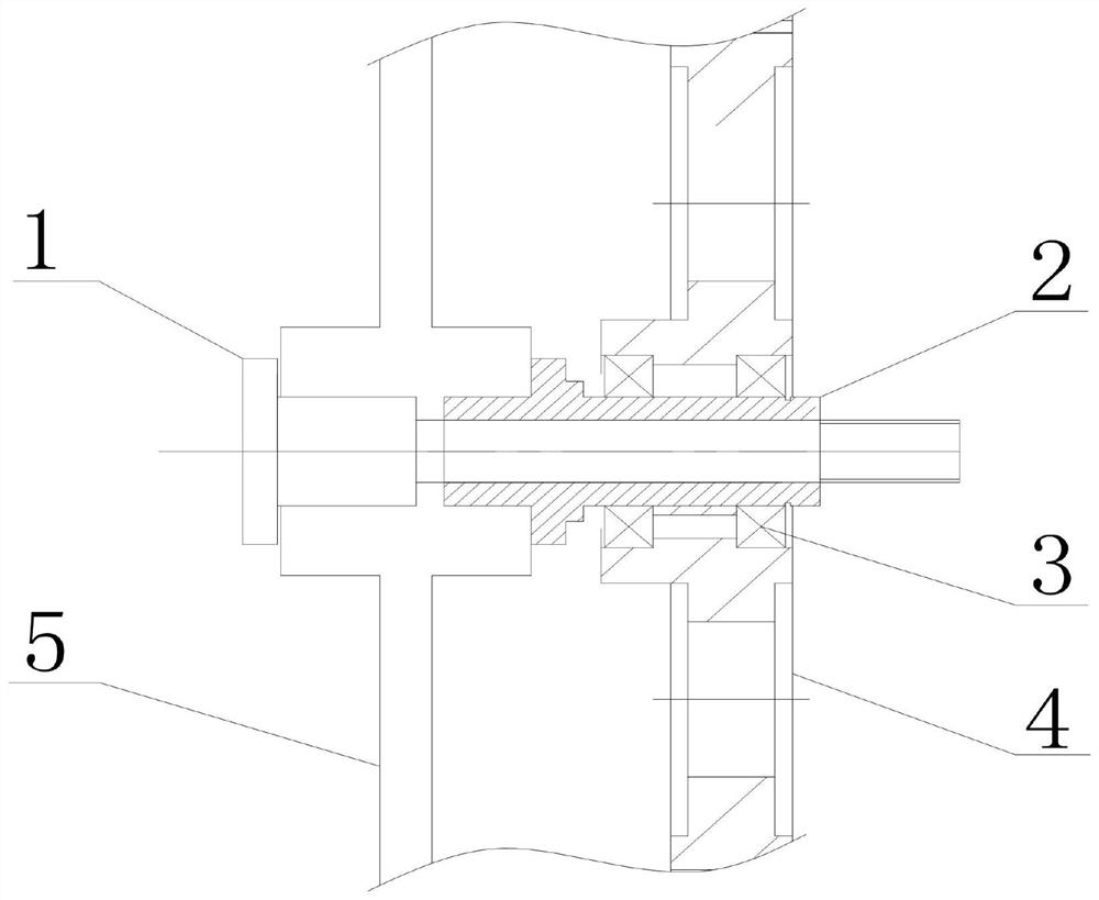
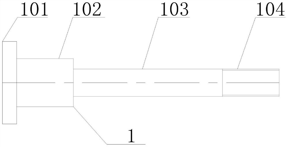
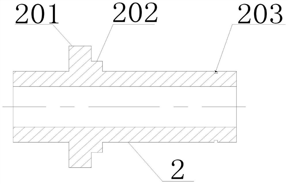
The invention discloses a connecting device for a stranding machine, which comprises a connecting shaft for connecting a stranding cage brake disc and a carrier gear, wherein the connecting shaft is sleeved with a shaft sleeve matched with the connecting shaft, the periphery of the shaft sleeve is provided with a first convex part and a second convex part, and the connecting shaft is arranged in the shaft sleeve in a close fit way. According to the invention, the gear of the stranding machine does not shake in the high-speed rotation process.

Description

technical field [0001] The invention relates to a component of cable manufacturing equipment, in particular to a connection device used on a stranding machine. Background technique [0002] In the field of cable manufacturing, it is necessary to twist and shape multi-core wires so that the twisted multi-core wires are round and the twisted lines are symmetrical and uniform. [0003] In the process of stranding multiple single-core wires, a 400 / 6+12+18 cage type stranding machine is often used. This equipment has a total of 3 strands with 6 strands, 12 strands, and 18 strands. The body can meet the twisting system of 36 wires. Capable of producing copper-aluminum stranded wire, steel-cored aluminum stranded wire, and insulated wire core, it is an indispensable production equipment for cable manufacturing. Due to the high utilization rate of the equipment, the three strands are all driven by gears, and the transmission shafts and bearings of the bridge gears are easy to wear...

Claims


Application Information

Patent Timeline
Patent Type & Authority Applications(China)
IPC IPC(8): H01B13/02
CPCH01B13/0207
Inventor 李娟邵伟洪毕远明陈雪峰田磊
Owner CHONGQING TAISHAN CABLE
Learn More