Wearable equipment based on intelligent glasses

A wearable device and smart glasses technology, applied in optical components, optics, instruments, etc., can solve the problems of unstable glasses erection, simple wearing method, poor practicability, etc., to avoid shaking, increase comfort, and reduce gravity effect of load

Inactive Publication Date: 2020-11-27
李俊
View PDF1 Cites 1 Cited by
  • Summary
  • Abstract
  • Description
  • Claims
  • Application Information

AI Technical Summary

Problems solved by technology

[0004] Aiming at the deficiencies of the prior art, the present invention provides a wearable device based on smart glasses, which solves the problem that the wearing method of the comparison file is too simple, the glasses are erected unstable, and are easy to fall with the movement of the wearer, and the practicability is not good The problem

Method used


Image

  • Wearable equipment based on intelligent glasses
  • Wearable equipment based on intelligent glasses
  • Wearable equipment based on intelligent glasses

Examples


Embodiment 1

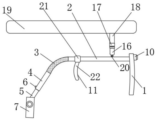
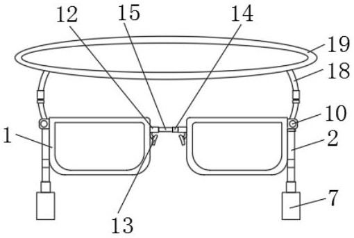
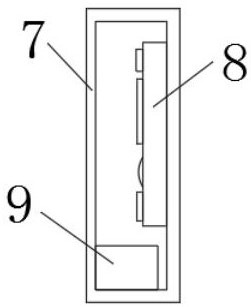
[0023] The embodiment of the present invention provides a wearable device based on smart glasses, including two separate lenses 1, a camera 10 is mounted on the front of the lens 1, a temple 2 is fixedly connected to the side wall of the lens 1, and the temple 2 is away from the lens One end of 1 is fixedly connected with a snake skin tube 3, the other end of the snake skin tube 3 is connected with a sleeve rod 4, the end of the sleeve rod 4 is inserted with an inner rod 5, and the side wall of the inner rod 5 is fixedly installed with an elastic switch 6 The elastic switch 6 is a micro switch, such as a button switch on an umbrella. The outer wall of the sleeve rod 4 is provided with a through hole adapted to the elastic switch 6, and the elastic switch 6 extends from the side of the inner rod 5 to the outside of the sleeve rod 4. , The bottom end of the inner rod 5 is fixedly connected with a protective shell 7, and the inside of the protective shell 7 is fixedly installed wit...

Embodiment 2

[0029] The difference from embodiment 1 is that the side wall of the temple 2 is connected with a chain 20, the side wall of the temple 2 is movably connected with a bottom belt 16 through the chain 20, and the top of the bottom belt 16 is movably connected with a top belt 18 through a buckle 17 , The top of the top strap 18 is fixedly connected with an elastic ring 19, wear the elastic ring 19 on the head, connect the top strap 18 at the bottom of the elastic ring 19 to the bottom strap 16 through the buckle 17, then the elastic ring 19 can be connected to the temple 2 is connected, and the lens 1 is also fixed on the wearer's face, which increases the wearing mode, improves the sustainable use effect of the device, and has better practicality.

[0030] Working principle: When in use, place the temple 2 on the wearer's ear, and adjust the length of the sleeve rod 4 and the inner rod 5 through the elastic switch 6, and the distance between the protective shell 7 and the lens 1 can...


PUM


Abstract

The invention relating to the technical field of intelligent equipment provides wearable equipment based on intelligent glasses. The wearable equipment based on intelligent glasses Comprises two independently separated lenses, a camera is mounted on the front surface of each lens; the side walls of the lenses are fixedly connected with glasses legs; the ends, away from the lenses, of the glasses legs are fixedly connected with flexible conduits; the other ends of the flexible conduits are connected with sleeve rods; inner rods are inserted into the end parts of the sleeve rods; and elastic switches are fixedly mounted on the side walls of the inner rods. According to the wearable equipment based on intelligent glasses, the length of the inner rod of the sleeve rod can be adjusted through the elastic switch; the distance between a protective shell and the lens is regulated and controlled, the ears are used as fulcrums to achieve balance, wearing of the equipment is stabilized, the gravity load of the glasses on the nose is reduced, wearing comfort is improved, the ends of magnetic rods are sleeved with iron pipes, the two independent lenses can be connected, and the situation that when the two lenses are worn at the same time, the angle difference between the two lenses is too large, and experience is influenced is avoided.

Description

Technical field [0001] The invention relates to the technical field of smart devices, in particular to a wearable device based on smart glasses. Background technique [0002] The so-called glasses are tools worn on the head, forehead and eyes to beautify the shape of the face, correct vision, and protect the eyes. Glasses (except for contact lenses) are smart glasses composed of lenses and temples. A wearable smart device that uses glasses as a carrier. Smart glasses have an independent operating system. Users can install software, games and other programs provided by software service providers, and can add schedules, map navigation, and interact with friends through voice or action control , Take photos and videos, start video calls with friends and other functions, and can achieve wireless network access through mobile communication networks, etc., a smart glasses and a wearable smart device with the application number CN201620331153.9, although the solution Excessive pressure...

Claims


Application Information

Patent Timeline
IPC IPC(8): G02B27/01
CPCG02B27/0172G02B27/0176G02B2027/0178
Inventor 李俊
Owner 李俊
Why Eureka
Try Eureka