A Pond Sewage Mechanism Designed for Landscape Architecture
A technology for sewage discharge mechanisms and ponds, which is applied in the field of gardening and can solve problems such as the decline of fish resistance, the death of pond organisms, and the unfavorable biological activities in the pond.
- Summary
- Abstract
- Description
- Claims
- Application Information
AI Technical Summary
Problems solved by technology
Method used
Image
Examples
Embodiment 1
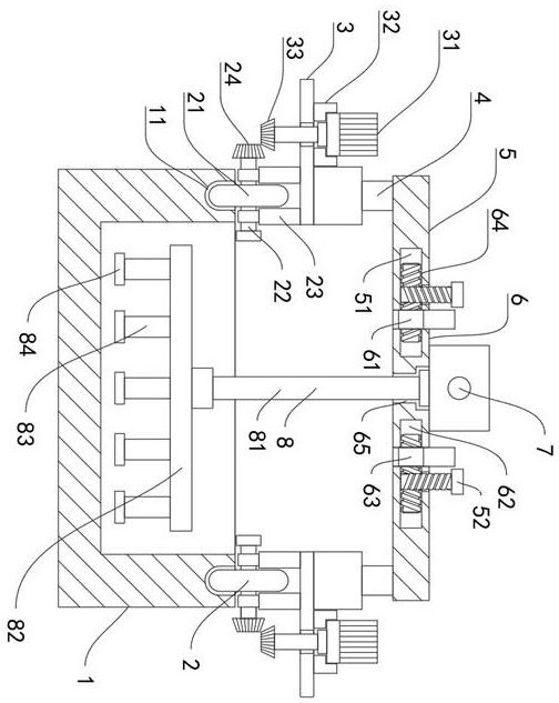
[0033] Such as Figure 1-5 As shown, a pond sewage discharge mechanism designed for landscape gardening includes rails 11 provided on the upper surface of both sides of the pond body 1, and the inner rotation of the upper end of the rail 11 is connected with a runner 2, and the runner 2 consists of runners 21, Rotating rod 22, connecting piece 23 is made up of, and rotating rod 22 perforations are connected in the middle part of running wheel 21, and the right end of rotating rod 22 is fixedly connected with limit block, and rotating rod 22 perforation is connected in the middle part of connecting part 23, and the upper end of connecting part 23 The surface is fixedly connected to the bottom surface of the lower end of the support plate 3 , and a driven inclined wheel 24 is fixedly connected to the end surface on the left side of the rotating rod 22 .
[0034] The upper surface of the runner part 2 is fixedly connected with a support plate 3, the lower end of the front side of...
Embodiment 2
[0038] Such as Image 6 As shown, the difference between this embodiment and Embodiment 1 is that the lower end of the support plate 3 is fixedly connected with a floating ball 34, the inner side of the support plate 3 is fixedly connected with a horizontal plate 35, and the middle part of the horizontal plate 35 is provided with a through groove. The mud discharge main pipe 81 is perforated and connected in the through groove, and the floating ball 34 is fixedly connected on the bottom surface of the lower end of the horizontal plate 35 .
[0039] According to Example 1, such as Figure 1-5 As shown, the runners 2 at both ends of the device are placed on the rails 11 at both ends of the pond body 1, that is, the runners 21 are placed on the rails 11, wherein the fixed plate 5 and the connecting plate 6 are connected by rotating the first threaded rod 52 drives the second threaded rod 64 to rotate in the first groove 51 and the second groove 62 to realize the effect of shorte...
PUM
 Abstract
Description
Claims
Application Information
 - R&D
- Intellectual Property
- Life Sciences
- Materials
- Tech Scout
- Unparalleled Data Quality
- Higher Quality Content
- 60% Fewer Hallucinations
Browse by: Latest US Patents, China's latest patents, Technical Efficacy Thesaurus, Application Domain, Technology Topic, Popular Technical Reports.
© 2025 PatSnap. All rights reserved.Legal|Privacy policy|Modern Slavery Act Transparency Statement|Sitemap|About US| Contact US: help@patsnap.com


