Impact-resistant tensile power protection pipe and preparation method thereof
A technology for power protection and impact resistance, applied in the direction of electrical components, etc., can solve the problems of inconvenient insertion and removal of power cables, failure to guarantee the stability of power cables, impact resistance, and tensile performance, etc., to achieve small friction and improve resistance Shock, easy insertion and removal effect
- Summary
- Abstract
- Description
- Claims
- Application Information
AI Technical Summary
Problems solved by technology
Method used
Image

Examples
Embodiment 1
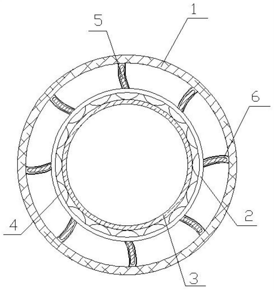
[0025] Such as figure 1 As shown, the present embodiment provides an impact-resistant and tensile-resistant power protection tube, which includes an outer sheath tube 1, an inner sheath tube 2, and an inner smooth tube 3 arranged in sequence from outside to inside. The inner smooth tube 3 is used to fix the power For the cable, wear-resistant protrusions 4 are distributed in an annular array between the inner sheath tube 2 and the inner smooth tube 3, inserting parts 5 are distributed in the peripheral annular array of the inner smooth tube 3, and the inner peripheral annular array of the outer sheath tube 1 is distributed with The engaging part 6 matched with the insertion part 5 . The power protection tube is provided with a structure from the outside to the inside and outside of the sheath tube 1, the inner sheath tube 2, and the inner smooth tube 3, and the wear-resistant protrusions 4 are distributed in an annular array between the inner sheath tube 2 and the inner smooth...
Embodiment 2
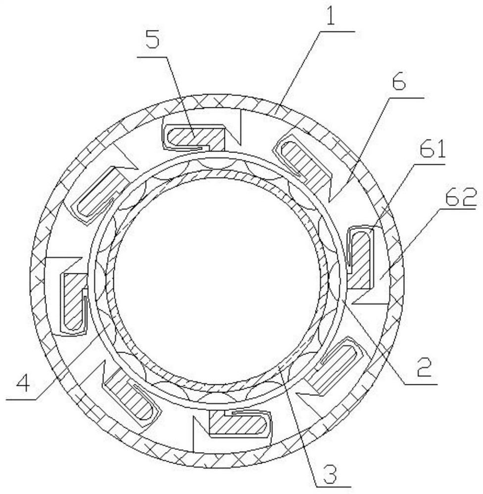
[0039] Such as figure 2 As shown, in the anti-shock and tensile power protection tube of this embodiment, the cross section of the insertion part 5 is L-shaped, and the engaging part 6 includes a U-shaped slot 61 for accommodating the insertion part 5 and a stopper for restricting the movement of the insertion part 5 plate 62. Of course, the structures of the insertion part 5 and the engaging part 6 are not limited to the above-mentioned embodiments, and can also be realized by other detachable assembly structures.
Embodiment 3
[0041] Such as Figure 1-2 As shown, this embodiment provides a preparation method for an impact-resistant and tensile-resistant power protection tube, including the following steps:
[0042] a. Preparation of the outer sheath tube: According to parts by weight, mix 42 parts of high-density polyethylene, 19 parts of polybutylene terephthalate, and 3 parts of vinyl glycidyl ether at 46 ° C and 250 rpm to mix evenly , add 9 parts of impact modifier, 8 parts of white carbon black, 5 parts of hydrophobic silica, 2.2 parts of carboxylic acid type compatibilizer, heat up to 66 ° C, stir at 400 rpm for 2.6 hours, extrude and granulate, Then use a molding extruder to extrude to obtain an outer sheath tube; wherein, the impact modifier is prepared from the following raw materials in parts by weight: 50 parts of polystyrene resin, 16 parts of nano-titanium dioxide, 10 parts of zeolite powder, gas phase two 7 parts of silicon oxide.
[0043] b. Preparation of inner sheath tube: 28 part...
PUM
 Abstract
Description
Claims
Application Information
 - Generate Ideas
- Intellectual Property
- Life Sciences
- Materials
- Tech Scout
- Unparalleled Data Quality
- Higher Quality Content
- 60% Fewer Hallucinations
Browse by: Latest US Patents, China's latest patents, Technical Efficacy Thesaurus, Application Domain, Technology Topic, Popular Technical Reports.
© 2025 PatSnap. All rights reserved.Legal|Privacy policy|Modern Slavery Act Transparency Statement|Sitemap|About US| Contact US: help@patsnap.com