


Quick Research
Generate reliable direction feasibility study reports for your R&D in just a few steps.

Technical Q&A
Discover and master advanced knowledge NOW. Basics, ideas, possibilities, all at once.

Find Solutions
As an expert in R&D theories, this can generate solutions to your technical problems instantly.

Evaluate Feasibility
Analyze your overall solution with one click, know your potential R&D risks in advance.

Monitor Landscape
Get weekly tech updates, stay abreast of the latest tech innovations and key insights.
Transmission mechanism
A transmission mechanism and internal sliding technology, applied in transmission devices, mechanical equipment, belts/chains/gears, etc., can solve the problems of complex hinge link transmission, and the limit mechanism cannot realize transmission well, and achieve the scope of improvement. , the effect of avoiding space problems
- Summary
- Abstract
- Description
- Claims
- Application Information
AI Technical Summary
Problems solved by technology
Method used
Image

Examples
Embodiment 1
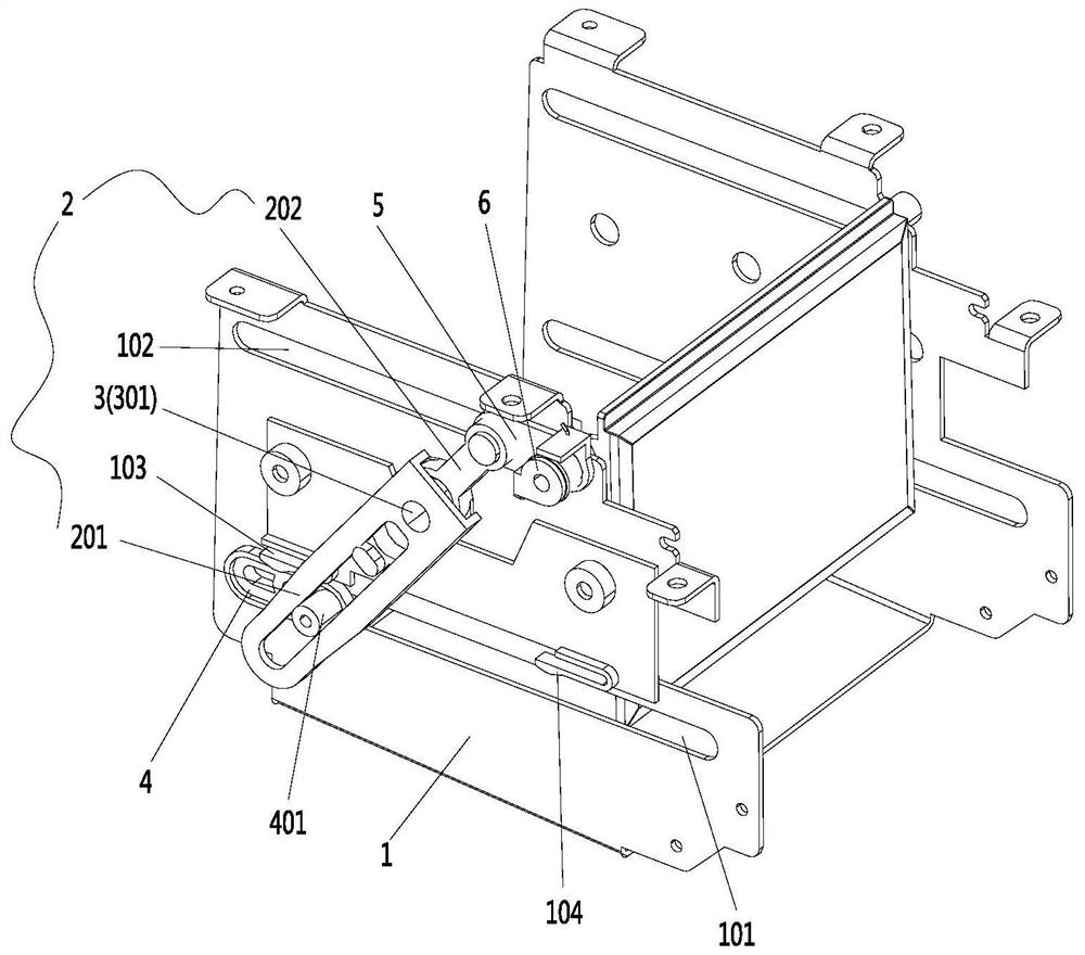
[0076] Such as Figure 1 to Figure 9 As shown, a transmission mechanism described in this embodiment includes a base 1 provided with a first chute 101 and a second chute 102; it also includes a connecting rod assembly 2 capable of rotating around a rotation center 3; the first The slider 4 and the second slider 5 are movably arranged on the connecting rod assembly 2, and can slide correspondingly to the first chute 101 and the second chute 102; wherein, the first slider 4 The sliding in the first sliding slot 101 drives the second sliding block 5 to slide in the second sliding slot 102 synchronously through the connecting rod assembly 2 .
[0077] Further, the connecting rod assembly 2 includes a first connecting rod 201 and a second connecting rod 202; the first connecting rod 201 cooperates with the rotating shaft 301 and can rotate around the rotating center 3; the first connecting rod When 201 rotates around the rotation center 3 , the second connecting rod 202 can extend...
Embodiment 2
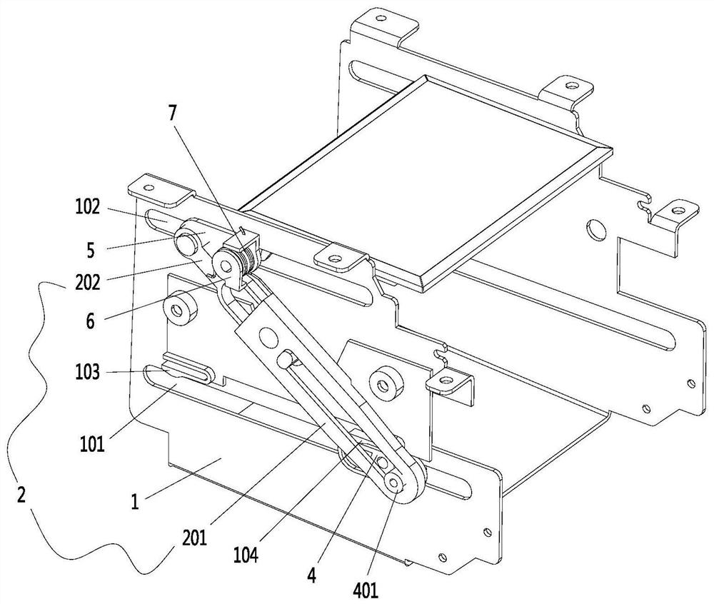
[0085] Such as Figure 1 to Figure 9 As shown, a transmission mechanism described in this embodiment includes a base 1; a connecting rod assembly 2 capable of rotating around a rotation center 3; a driving unit connected to the connecting rod assembly 2; a first slider 4, It is movably arranged on the connecting rod assembly 2, and can slide in the chute of the base 1; wherein, the driving unit drives the connecting rod assembly 2 to rotate around the rotation center 3, and cooperates with the first The sliding of a slider 4 on the connecting rod assembly 2 defines the sliding track of the first slider 4 in the sliding groove of the base 1 .
Embodiment 3
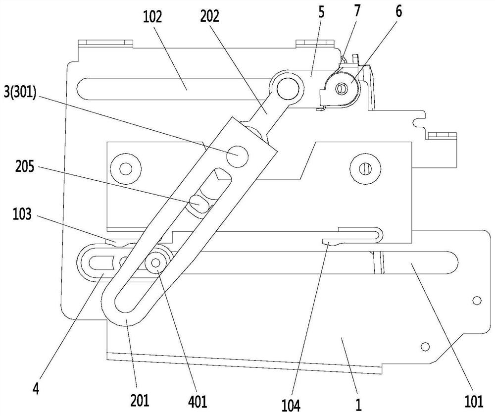
[0087] Such as Figure 1 to Figure 9 As shown, this embodiment is based on the above-mentioned second embodiment. The transmission mechanism also includes a second slider 5, which is movably arranged on the connecting rod assembly 2 and can be positioned on the base 1. sliding in the chute; the driving unit drives the connecting rod assembly 2 to rotate around the rotation center 3, cooperates with the sliding of the second sliding block 5 on the connecting rod assembly 2, and defines the second sliding The sliding track of the block 5 in the chute of the base 1; the base 1 includes a first chute 101 and a second chute 102; the first slider 4 and the second slider 5 correspond to The first chute 101 and the second chute 102 are slidably arranged.
[0088] Further, the connecting rod assembly 2 includes a first connecting rod 201 and a second connecting rod 202; the first connecting rod 201 cooperates with the rotating shaft 301 and can rotate around the rotating center 3; the...
PUM
 Abstract
Description
Claims
Application Information
 - R&D Engineer
- R&D Manager
- IP Professional
- Industry Leading Data Capabilities
- Powerful AI technology
- Patent DNA Extraction
Browse by: Latest US Patents, China's latest patents, Technical Efficacy Thesaurus, Application Domain, Technology Topic, Popular Technical Reports.
© 2024 PatSnap. All rights reserved.Legal|Privacy policy|Modern Slavery Act Transparency Statement|Sitemap|About US| Contact US: help@patsnap.com