Water-saving flushing tank
A technology for flushing water tanks and water tanks, which is applied to flushing equipment with water tanks, water supply devices, water resources protection and other directions, can solve the problems of unsatisfactory water saving effect, uncontrollable flushing volume, large water consumption, etc., and achieves simple structure and operation. Stabilizing and saving water resources
- Summary
- Abstract
- Description
- Claims
- Application Information
AI Technical Summary
Problems solved by technology
Method used
Image
Examples
Embodiment 1
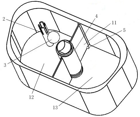
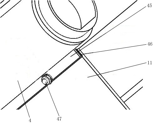
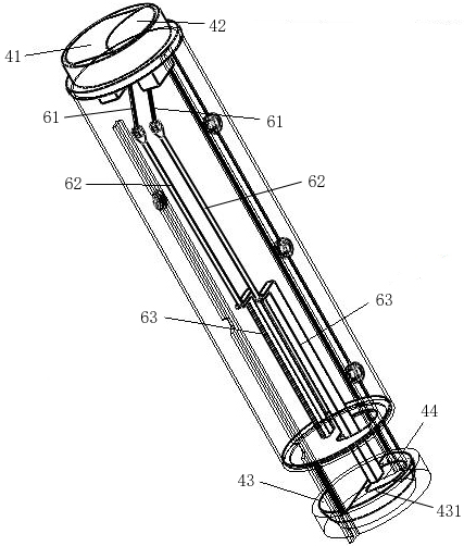
[0028] Such as figure 1 As shown, a water-saving flushing tank is provided, which includes a water tank, a water inlet valve 2, a float 3 and a drain valve 4. A partition 11 is provided between the outer periphery of the drain valve 4 and the wall of the water tank to divide the inner cavity of the water tank into two The first water tank 12 and the second water tank 13 are formed, the first water tank 12 is a small flow drainage tank, the second water tank 13 is a large flow drainage tank, the water inlet valve 2 and the floating ball 3 are located in the first water tank 12, and the floating ball 3 Adjustment function, the water surface drives the floating ball 3 to a certain height, the water inlet valve 2 is closed, the water surface drives the floating ball 3 to lower, and the water inlet valve 2 is opened to replenish water; the partition 11 is installed near the bottom of the water tank to supply water from the first water tank 12 The one-way valve 5 of the second water...
Embodiment 2
[0042] The difference between this embodiment and Embodiment 1 is: the large drainage button and the small drainage button respectively control the drainage of the large flow drainage plug and the small flow drainage plug through the rack and pinion mechanism, such as Figure 5 with Image 6 As shown, the rack and pinion mechanism is installed between the connecting rod 62 and the plug rod 63. Specifically, the rack and pinion mechanism includes a first pull rod 71 connected to the connecting rod at the large drain button 41, and connected to the small drain button 42. The second pull rod 72 where the rods are connected, the ends of the first pull rod and the second pull rod are respectively provided with a first gear 73 and a second gear (not shown), and the ends of the first / second pull rod respectively have The bent end 75 of the gear center hole, the rack and pinion mechanism also includes a fixed rack 76 fixed in the drain valve, the first gear 73 and the second gear can ...
PUM
 Abstract
Description
Claims
Application Information
 - R&D
- Intellectual Property
- Life Sciences
- Materials
- Tech Scout
- Unparalleled Data Quality
- Higher Quality Content
- 60% Fewer Hallucinations
Browse by: Latest US Patents, China's latest patents, Technical Efficacy Thesaurus, Application Domain, Technology Topic, Popular Technical Reports.
© 2025 PatSnap. All rights reserved.Legal|Privacy policy|Modern Slavery Act Transparency Statement|Sitemap|About US| Contact US: help@patsnap.com


