Hoisting device for automatic equipment installation

A technology of automation equipment and lifting devices, which is applied in the direction of lifting equipment braking devices, safety devices, hoisting devices, etc., can solve the problems of high cost and power consumption, and achieve acceleration and stop, strong magnetic force, and increased inertia. Effect

Inactive Publication Date: 2020-11-24
南京奥亚美电子科技有限公司
View PDF0 Cites 2 Cited by
  • Summary
  • Abstract
  • Description
  • Claims
  • Application Information

AI Technical Summary

Problems solved by technology

[0003] During the transportation of automation equipment, it is often necessary to use hoisting equipment for transfer operations in order to improve the transfer efficiency. The existing hoisting equipment generally uses electric guide rails and other electrical appliances to operate the hoisting and moving process, although electric guide rails and other such electrical appliances have good output function, but there are defects such as high cost and power consumption. Therefore, corresponding improvements are made for this problem

Method used


Image

  • Hoisting device for automatic equipment installation
  • Hoisting device for automatic equipment installation
  • Hoisting device for automatic equipment installation

Examples


Embodiment 1

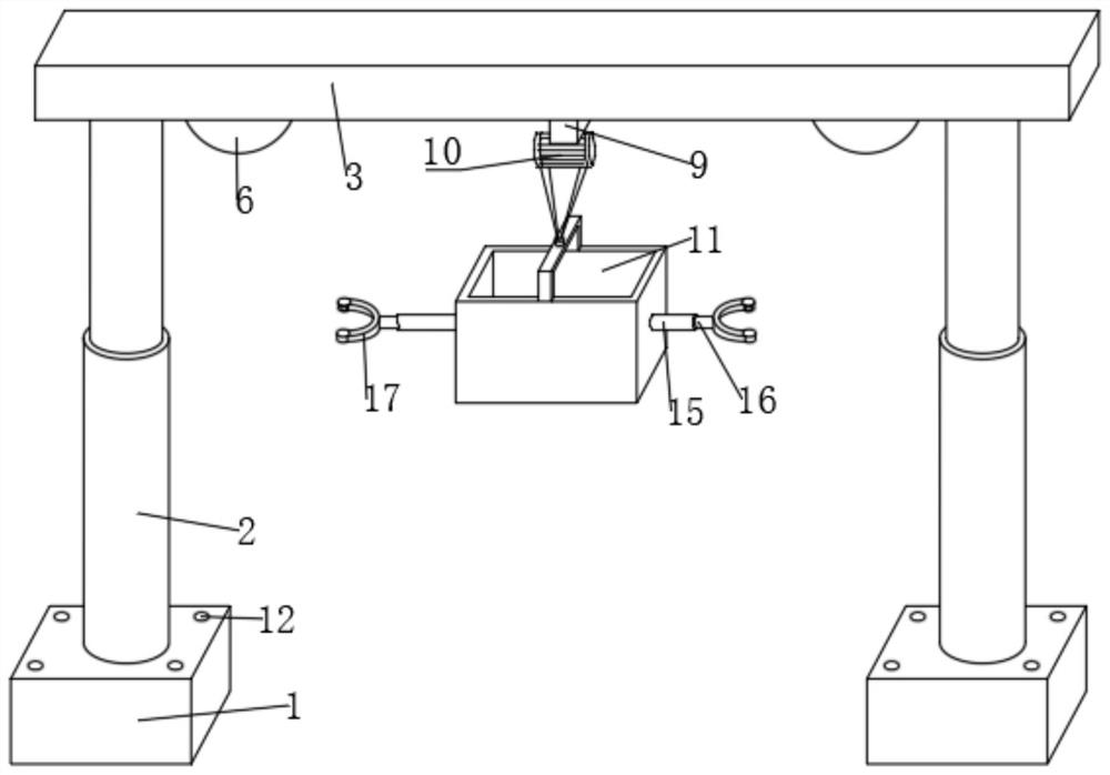
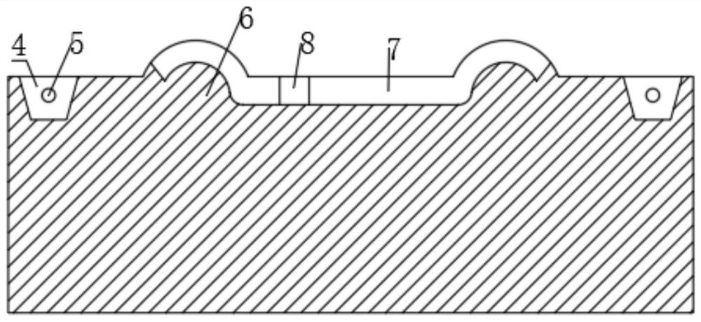
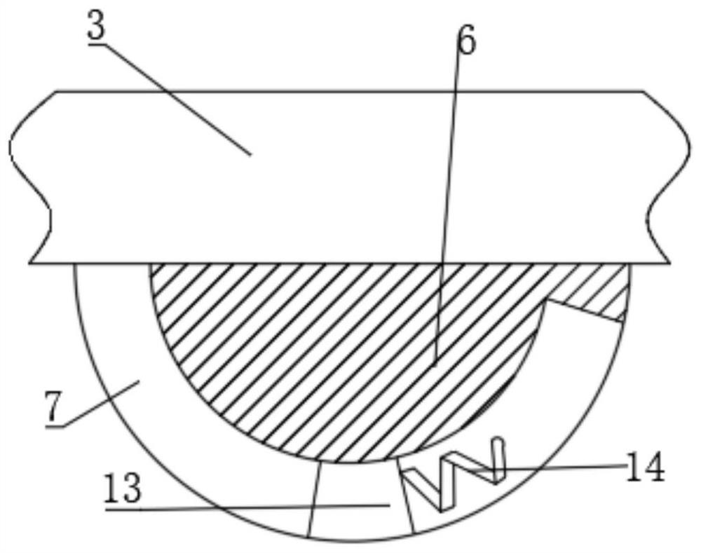
[0026] refer to Figure 1-3 , a hoisting device for installing automation equipment, comprising two bases 1, a hydraulic cylinder is fixed inside the base 1 by bolts, a hydraulic rod 2 is connected to the output end of the hydraulic cylinder, the hydraulic rod 2 and the base 1 are set through, and the two hydraulic rods 2 is set above the same lifting beam 3, and two notches 4 are symmetrically opened on both sides of the bottom of the lifting beam 3, and the notches 4 are set in a flared structure, and the straight shaft 5 is fixed in the notch 4 by bolts, and the hydraulic rod 2. The output shaft and the straight shaft 5 are nested and flexibly connected. Two deceleration bumps 6 are welded symmetrically on both sides of the bottom of the lifting beam 3. The deceleration bump 6 and the bottom of the inner wall of the lifting beam 3 are provided with the same first chute 7. The cross-section of the first chute 7 located on the deceleration bump 6 is set in an arc shape. The f...

Embodiment 2

[0030] refer to Figure 1-5 , a lifting device for the installation of automation equipment, 4 the first chute 7 is slidingly connected with a block 13, the outside of the block 13 is fixed with a first spring 14 by bolts, and the anti-collision mechanism passes symmetrically on both sides of the lifting box 11 Bolts are fixed with two sleeves 15, the sleeves 15 are sleeved with an inner rod 16, and the outer side of the inner rod 16 is bonded with a speed-reducing claw 17, which is made of rubber material, and the speed-reducing claw 17 is arranged as a fork structure The deceleration mechanism is provided with an embedded groove 18 in the casing 15, the inner rod 16 is arranged in the embedded groove 18, the bottom of the inner wall of the embedded groove 18 is fixed with a second spring 19 by bolts, and the top of the second spring 19 and the bottom of the inner rod 16 are welded and fixed The inner wall of one side of the embedded groove 18 is provided with a second chute ...


PUM


Abstract

The invention belongs to the technical field of automatic equipment, particularly relates to a hoisting device for automatic equipment installation, and aims at solving the problem that an existing device consumes electric energy. According to the scheme, the hoisting device comprises two bases, hydraulic cylinders are fixed in the bases, the output ends of the hydraulic cylinders are connected with hydraulic rods, and the same hoisting beam is arranged above the two hydraulic rods; and two notches are symmetrically formed in the two sides of the bottom of the hoisting beam, straight shafts are fixed in the notches, output shafts of the hydraulic rods are movably connected with the straight shafts in a nested mode, a first sliding groove is formed in the bottom of the inner wall of the hoisting beam, a first sliding block is slidably connected into the first sliding groove, and a hoisting mechanism is connected to the bottom of the first sliding block. According to the hoisting device,the hydraulic cylinders are started to drive the hydraulic rods to do telescopic movement, so that the two hydraulic rods are located at different vertical heights, a hoisting box is pushed, the hoisting box can move along the inclined hoisting beam along with the first sliding block under the action of gravity, and hoisting can be conducted under the condition that electric driving is not needed.

Description

technical field [0001] The invention relates to the technical field of automation equipment, in particular to a hoisting device for installing automation equipment. Background technique [0002] Automation technology is widely used in industry, agriculture, military, scientific research, transportation, commerce, medical care, services and households. The use of automation technology can not only liberate people from heavy physical labor, part of mental work, and harsh and dangerous working environments, but also expand human organ functions, greatly improve labor productivity, and enhance human ability to understand and transform the world. . [0003] During the transportation of automation equipment, it is often necessary to use hoisting equipment for transfer operations in order to improve the transfer efficiency. The existing hoisting equipment generally uses electric guide rails and other electrical appliances to operate the hoisting and moving process, although electr...

Claims


Application Information

Patent Timeline
Patent Type & Authority Applications(China)
IPC IPC(8): B66C19/00B66C15/04B66C5/04
CPCB66C5/04B66C15/04B66C19/00
Inventor 刘洁珍
Owner 南京奥亚美电子科技有限公司
Why Eureka
Try Eureka