Auxiliary speed reducer for downhill of heavy-duty truck

A technology for deceleration devices and trucks, which is applied to vehicle components, transportation and packaging, and brakes. It can solve problems such as thermal decline of braking capacity, prolonging the braking distance of trucks, and overheating of the braking system, so as to reduce brake failure accidents and reduce Rolling risk and losses caused by rolling, and the effect of reducing the overall temperature

Inactive Publication Date: 2020-11-24
张国蓉
View PDF0 Cites 0 Cited by
  • Summary
  • Abstract
  • Description
  • Claims
  • Application Information

AI Technical Summary

Problems solved by technology

[0003] For heavy-duty trucks, after continuous braking, due to frictional heat, the braking ability of the brakes will undergo obvious thermal decline, and it will not be able to provide enough braking force to stop the truck in time, especially when going downhill for a long time, not only cannot slow down , and under the action of gravity acceleration, the truck will continue to accelerate and make the truck out of control. Therefore, the continuous long downhill is a test of the experience of the truck driver. Therefore, even experienced drivers may experience brake failure caused by the overheating of the brake system during the long downhill process.
[0004] On the other hand, the actual process of braking causes the brake device to reduce the wheel speed through friction, and the friction between the wheel and the ground will slow down the entire vehicle. Therefore, in addition to the heat of the brake device and the decline in braking force, the wheels and the ground will Heat will reduce the friction between the wheels and the ground, and will also prolong the braking distance of the truck, making it impossible to stop in time

Method used


Image

  • Auxiliary speed reducer for downhill of heavy-duty truck
  • Auxiliary speed reducer for downhill of heavy-duty truck
  • Auxiliary speed reducer for downhill of heavy-duty truck

Examples


Embodiment Construction

[0021] The following will clearly and completely describe the technical solutions in the embodiments of the present invention with reference to the accompanying drawings in the embodiments of the present invention. Obviously, the described embodiments are only some of the embodiments of the present invention, not all of them. Based on the embodiments of the present invention, all other embodiments obtained by persons of ordinary skill in the art without making creative efforts belong to the protection scope of the present invention.

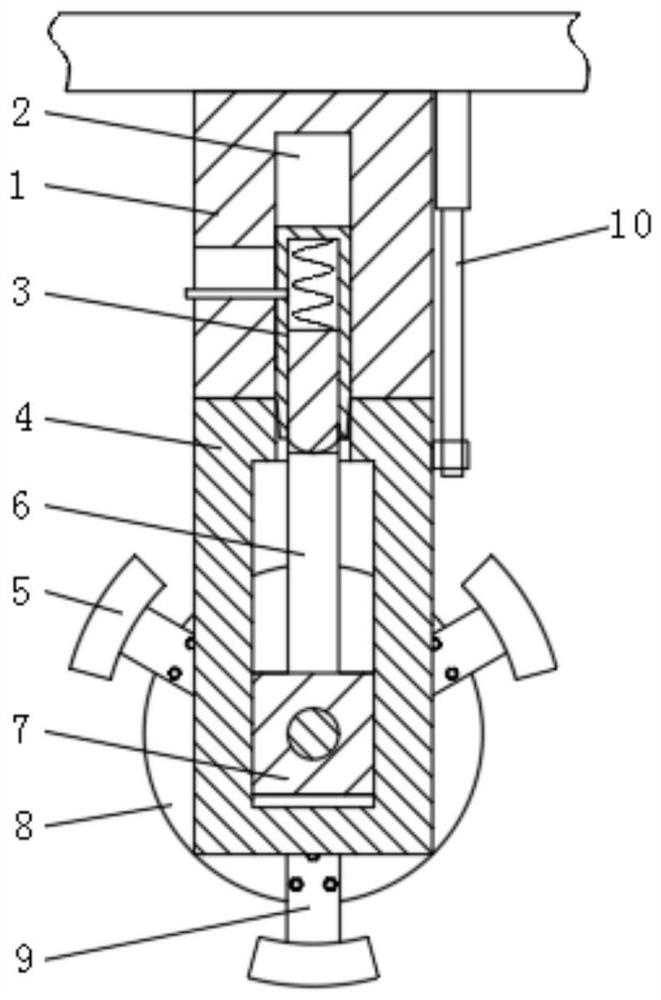
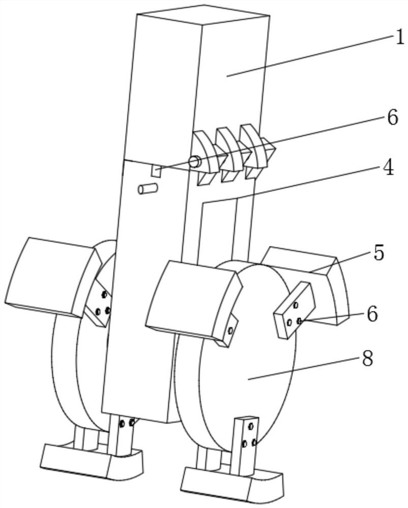
[0022] see figure 1 , an auxiliary deceleration device for downhill use of a truck, comprising a fixed base 1 fixedly installed on the chassis of the truck, a positioning cylinder 2 fixedly connected to the inside of the positioning cylinder 2, and the positioning cylinder 2 provides hydraulic pressure through the hydraulic system of the vehicle. Oil, the piston rod of the positioning cylinder 2 is fixedly connected with the deceleration cylinder...


PUM


Abstract

The invention relates to the technical field of braking equipment, and discloses an auxiliary speed reducer for a downhill of a heavy-duty truck. The auxiliary speed reducer comprises a fixed seat fixedly mounted on a chassis of the truck, and a vertically arranged positioning cylinder is fixedly connected inside a positioning cylinder. According to the auxiliary speed reducer for the downhill ofthe heavy-duty truck, on the occasions of the long downhill or other occasions needing continuous braking, kinetic energy generated when the truck advances can be effectively converted into heat energy of hydraulic oil for auxiliary braking, meanwhile, gravitational acceleration during downhill can be counteracted, and normal running of the truck is guaranteed on the premise that braking is not frequently stepped on; according to the device, friction is conducted in turn through three connecting frames, local overheating is avoided, meanwhile, the heat dissipation capacity of hydraulic oil isenhanced, the overall temperature is reduced, the heating influence is small, the device is far away from a hub, the phenomena of tire explosion, axle deformation and the like caused by overheating are avoided, and on the other hand, when a vehicle is parked on a ramp, the vehicle sliding risk can be reduced through the device.

Description

technical field [0001] The invention relates to the technical field of brake equipment, in particular to an auxiliary deceleration device for downhill use of a truck. Background technique [0002] The braking device of a truck is usually a drum brake or a disc brake. The basic principle is to use hydraulic oil to provide the braking torque, make the friction plate and the friction force close, and use the friction force to release the heat energy converted from the kinetic energy of the car, so the brake Usually accompanied by heat production. [0003] For heavy-duty trucks, after continuous braking, due to frictional heat, the braking ability of the brakes will undergo obvious thermal decline, and it will not be able to provide enough braking force to stop the truck in time, especially when going downhill for a long time, not only cannot slow down , and under the action of gravity acceleration, the truck will continue to accelerate and make the truck out of control. Theref...

Claims


Application Information

Patent Timeline
IPC IPC(8): B60T1/14
CPCB60T1/14
Inventor 张国蓉
Owner 张国蓉
Why Eureka
Try Eureka