
3300V high-voltage permanent magnet variable frequency motor all-in-one machine

A variable frequency motor and integrated machine technology, which is applied in the direction of electric components, electromechanical devices, electrical components, etc., can solve problems such as troublesome use and excessive accumulation of motor dust, reduce the steps of water cooling and heat dissipation, enhance heat conduction, and simplify the structure of water cooling and heat dissipation effect

Active Publication Date: 2020-11-20
浙江开泰新能源科技有限公司
View PDF10 Cites 3 Cited by
  • Summary
  • Abstract
  • Description
  • Claims
  • Application Information

AI Technical Summary

Problems solved by technology

[0005] In order to make up for the deficiencies of the existing technology, when the existing high-voltage permanent magnet variable frequency motor integrated machine is used in the mine environment, on the one hand, the air-cooling mechanism tends to cause excessive dust accumulation inside the motor, and at the same time, the water-cooling mechanism needs external water pumps and other equipment. The use of more troublesome problems in mines, a 3300V high-voltage permanent magnet variable frequency motor integrated machine proposed by the present invention

Method used


Image

  • 3300V high-voltage permanent magnet variable frequency motor all-in-one machine
  • 3300V high-voltage permanent magnet variable frequency motor all-in-one machine
  • 3300V high-voltage permanent magnet variable frequency motor all-in-one machine

Examples


Embodiment approach

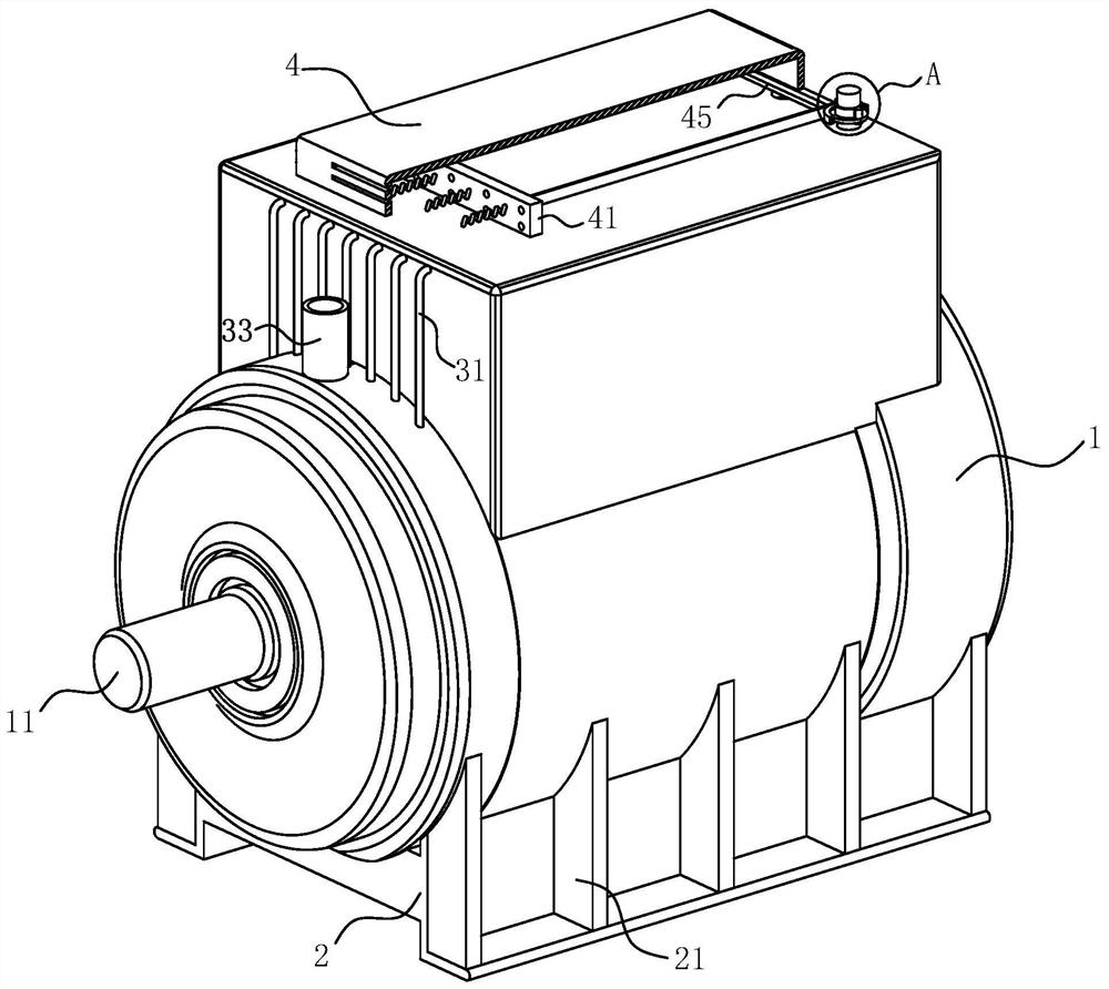
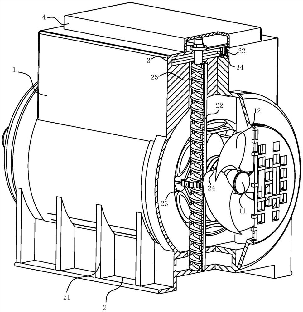
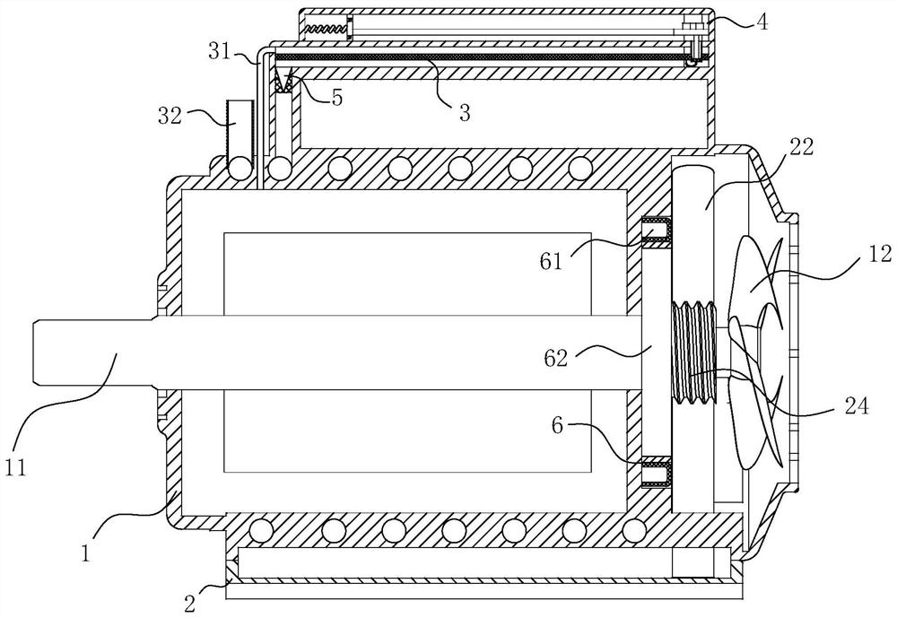
[0026] As an embodiment of the present invention, the air box 4 is fixedly connected to the top of the body; the air intake pipe 32 is designed to be located in the air box 4 at one end away from the casing 1; Pressing plate 41; said inflatable box 4 is designed with an opening close to the side of the extruding plate 41; said extruding plate 41 is provided with evenly distributed one-way through holes; Two through grooves; the second through groove and the first through groove conduction design; the second through groove is rotationally connected with a rotating shaft 42; the rotating shaft 42 is fixedly connected with the screw column 25; the rotating shaft 42 One end of the inflatable box 4 is sleeved with a toggle wheel 43; the toggle wheel 43 is designed in a "ten" shape; the outer side of the toggle wheel 43 is sleeved with a turning wheel 44; the turning wheel 44 and the toggle wheel 43 meshing design; the side of the rotating wheel 44 close to the extrusion plate 41 is...


PUM


Abstract

The invention belongs to the technical field of variable frequency motors, and particularly relates to a 3300V high-voltage permanent magnet variable frequency motor all-in-one machine which comprisesa machine shell, a frequency converter assembly and a permanent magnet synchronous motor assembly. The permanent magnet synchronous motor assembly comprises a stator, a rotor and a rotating shaft. Amotor cavity and a frequency conversion cavity are formed in the machine shell. The permanent magnet synchronous motor assembly and the motor cavity jointly form a permanent magnet synchronous motor.The frequency converter assembly is installed in the frequency conversion cavity. A heat dissipation cavity is formed in the end, located in the motor cavity, of the machine shell. A rotating shaft inthe permanent magnet synchronous motor assembly extends into the heat dissipation cavity. By arranging a water storage cavity and a circulating cavity and utilizing rotation of the rotating shaft, water flow in the lower water storage cavity is pumped into the circulating cavity through the water pumping pipe, after the water flow makes contact with the pumped outside air, the water flow flows into the heat exchange cavity, the air flow enters the motor cavity, and heat conduction between the permanent magnet synchronous motor assembly and the machine shell is effectively accelerated and enhanced.

Description

technical field [0001] The invention belongs to the technical field of variable frequency motors, in particular to a 3300V high-voltage permanent magnet variable frequency motor integrated machine. Background technique [0002] In the prior art, the high-voltage permanent magnet frequency conversion motor integrated machine combines the frequency converter and the permanent magnet synchronous motor to form an integration. Under the premise of greatly reducing the volume, the motor and the frequency converter can work together, reducing the need for using cables to combine frequency conversion. When using inverters and permanent magnet motors, the electromagnetic interference and power loss caused by cables are especially convenient when used in mines. However, due to the integration of permanent magnet motors and frequency converters, both work Heat will be generated, and the integrated setting puts forward greater requirements for heat dissipation. At the same time, there a...

Claims


Application Information

Patent Timeline
IPC IPC(8): H02K5/10H02K9/06H02K5/18H02K9/19H02K11/33B01D47/02
CPCB01D47/021H02K5/10H02K5/18H02K9/06H02K9/19H02K11/33Y02P70/10
Inventor 李乐东
Owner 浙江开泰新能源科技有限公司
Learn More