
High-gain differential dual-polarized antenna based on hollow dielectric patch resonator

A technology of patch resonator and dual-polarized antenna, which is applied in the direction of resonator, antenna grounding device, antenna grounding switch structure connection, etc., can solve the problem of not meeting the needs of broadband development.

Active Publication Date: 2020-11-20
NANTONG UNIVERSITY +1
View PDF3 Cites 6 Cited by
  • Summary
  • Abstract
  • Description
  • Claims
  • Application Information

AI Technical Summary

Problems solved by technology

In the patent "a high-gain differential dual-polarized dielectric patch antenna based on high-order mode" applied by the applicant, it involves a differentially fed dual-polarized dielectric patch antenna working in a high-order mode, and will Four ground rods are introduced into the resonator to achieve a gain of up to 9 dBi, but the bandwidth is less than 5%, which cannot meet the development needs of broadband

Method used


Image

  • High-gain differential dual-polarized antenna based on hollow dielectric patch resonator
  • High-gain differential dual-polarized antenna based on hollow dielectric patch resonator
  • High-gain differential dual-polarized antenna based on hollow dielectric patch resonator

Examples


Embodiment Construction

[0019] The present invention will be further described below in conjunction with the accompanying drawings and specific embodiments.

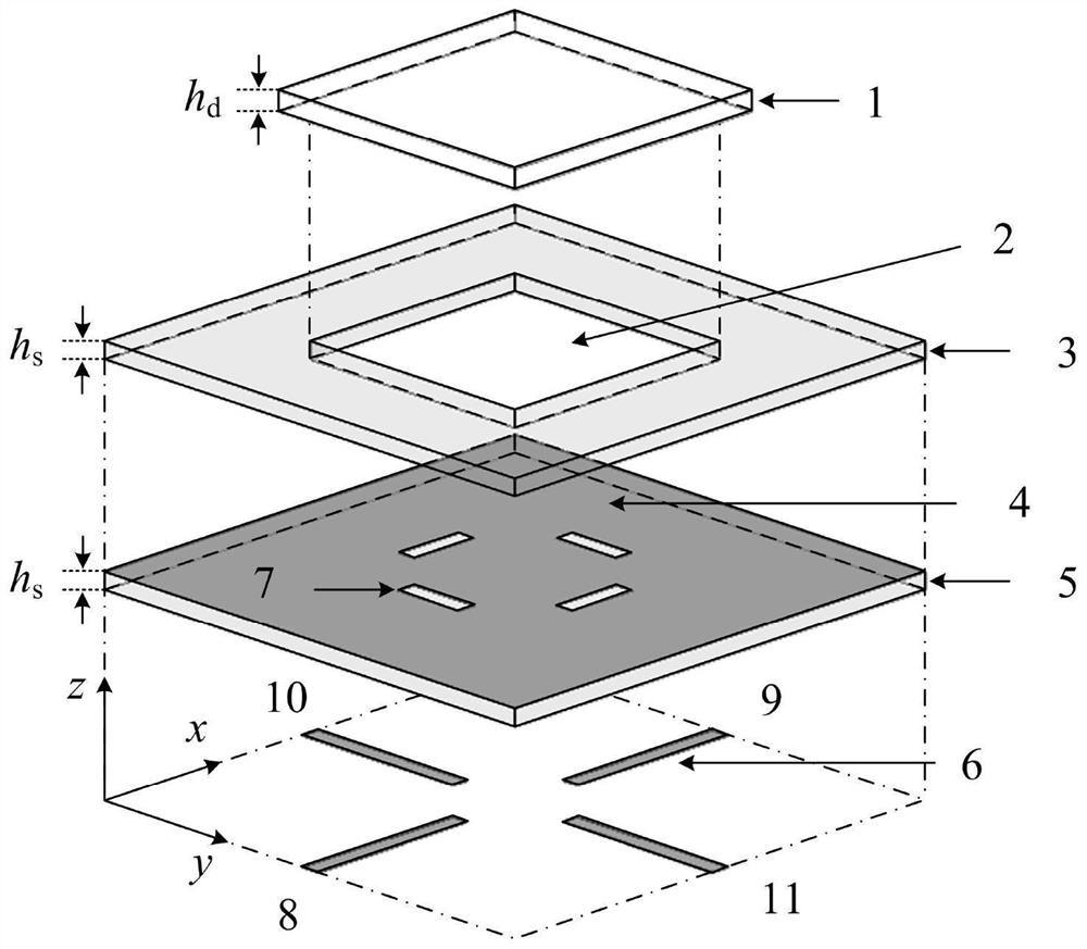
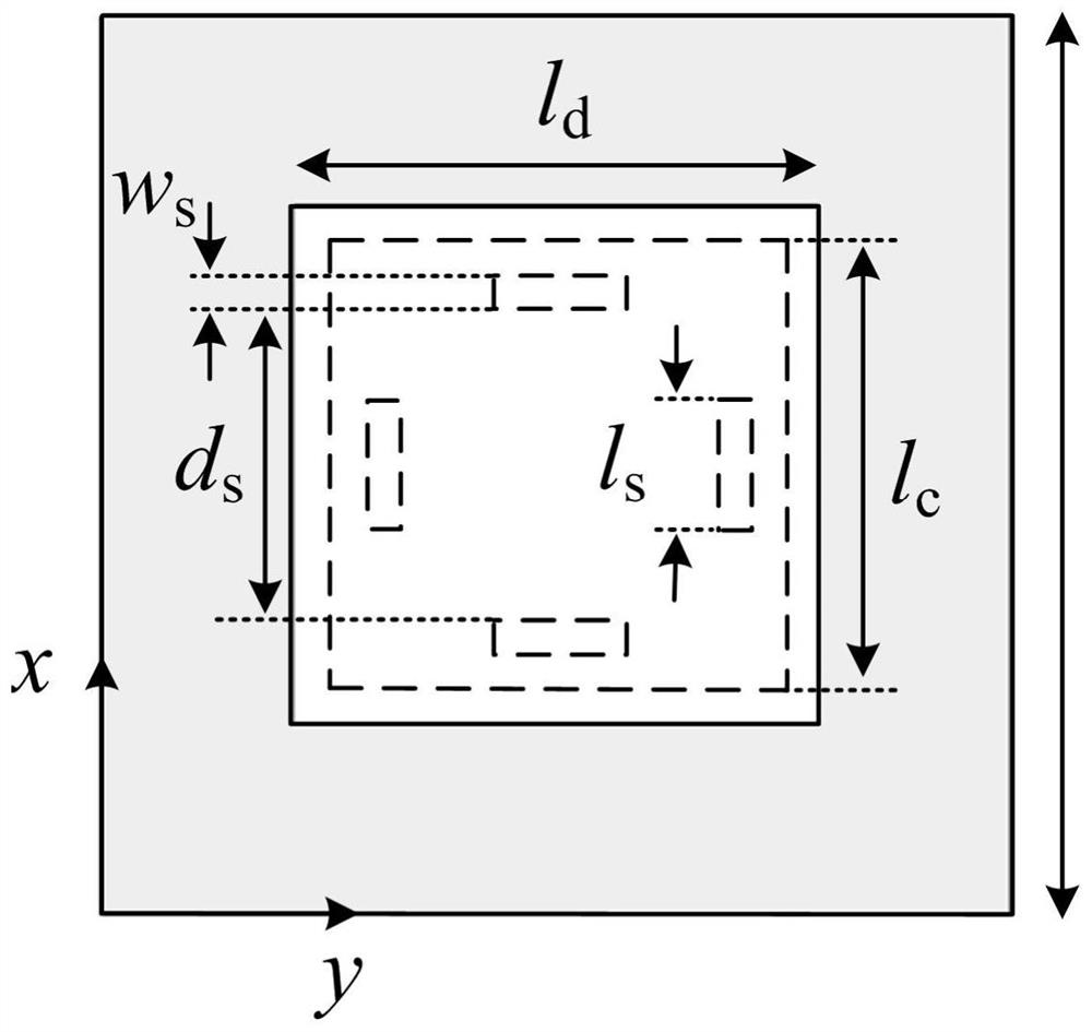
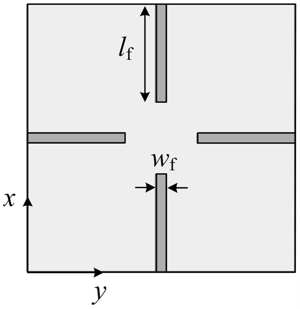
[0020] Such as Figure 1 to Figure 3 As shown, the differentially fed dual-polarized dielectric patch antenna in this embodiment is sequentially stacked with a lower dielectric substrate 5 , a metal reflective floor 4 , an upper dielectric substrate 3 and a square dielectric patch 1 . The dielectric constant of the square dielectric patch 1 is ε rd = 45, loss tangent tanδ = 1.9×10 -4 , with a volume of l d x l d x h d . Both the lower dielectric substrate 5 and the upper dielectric substrate 3 use Rogers RO4003, and the dielectric constant is ε rs = 3.38, the loss tangent is tanδ = 2.7×10 -3 , with a volume of l g x l g x h s . In order to obtain a relatively high gain, a volume of l c x l c x h s The square hole 2 is fused with the dielectric patch 1 to form a hollow dielectric patch resonator. The lower surface...


PUM


Abstract

The invention relates to a high-gain differential dual-polarized antenna based on a hollow dielectric patch resonator. The antenna comprises a lower dielectric substrate, a metal reflection floor, anupper dielectric substrate and a dielectric patch which are sequentially stacked from bottom to top; two pairs of microstrip feeders used for differential feeding are arranged on the lower surface ofthe lower dielectric substrate; a coupling gap is formed in the metal reflection floor; a square hole located under the dielectric patch is formed in the upper dielectric substrate; and the square hole and the dielectric patch are fused to form the hollow dielectric patch resonator. The square hole is formed below the dielectric patch to obtain the hollow dielectric patch resonator, electromagnetic radiation from the side wall of the dielectric patch resonator is increased to further improve gain, the main mode TM101 mode is moved upwards to be close to the high-order mode TM121 mode, and therefore bandwidth expansion is achieved.

Description

technical field [0001] The invention relates to a differentially fed dual-polarized dielectric patch antenna with high gain, wide band and high isolation, belonging to the technical field of wireless communication. Background technique [0002] With the development of wireless communication technology, characteristics such as miniaturization, low loss, broadband and high gain have become important indicators for antenna design. Microstrip patch antennas have been extensively studied due to their superior characteristics of low profile, light weight and relatively high gain. In order to increase the information transmission rate, the carrier frequency of the RF front-end is gradually increased, which makes the conductor loss of the microstrip patch antenna more serious and the radiation efficiency decreases. To solve this problem, dielectric resonator antennas with almost zero conductor loss have been extensively studied. However, conventional dielectric resonator antennas ...

Claims


Application Information

Patent Timeline
IPC IPC(8): H01Q1/38H01Q1/48H01Q1/50H01P7/10
CPCH01Q1/38H01Q1/48H01Q1/50H01P7/105
Inventor 陈建新王雪颖唐世昌杨永杰
Owner NANTONG UNIVERSITY
Learn More